3D Sketch
Status: Implemented
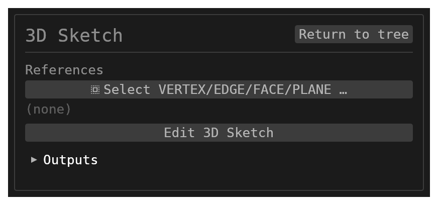
A 3D sketch holds points, lines, arcs and bezier chains in free space, held together by a 3D constraint solver and tied to the model through linked references: a vertex, an edge, a planar face, a datum plane or axis. On every regenerate it re-resolves those references, solves the geometry and publishes the result under its own name as paths, where Tube, Sweep and Path Sweep pick it up. It produces no solid of its own. It is the skeleton for tubular frames and the centreline for a routed harness or pipe run.
Inputs
id–string, defaultnull. Every name the sketch publishes is prefixed with it.references– multiplereference_selection(VERTEX,EDGE,FACEorPLANE, defaultnull). The model geometry the sketch is linked to. Each is materialised in the editor as fixed construction geometry (see Referencing model geometry); references linked with the editor's tool are written here, and a name listed here is linked on the next edit.editSketch3d–button, defaultnull, that opens the 3D sketch editor.
The geometry, constraints and working plane are not dialog fields; they are edited in the editor.
Entering and leaving 3D sketch mode
Edit 3D Sketch opens the editor in the 3D viewport. The model rolls back to the step
before the sketch, so the backdrop is the model as it stands underneath this
feature, and the 3D selection is cleared. The camera is left where it was: there is
no plane to face, you orbit freely while sketching, and Finish keeps the view you
ended on.
Finish and Cancel live in the shared top-right mode-exit card. Finish writes the
sketch, its reference records and the working plane back into the feature and lists
every linked reference in the dialog's references field; Cancel discards the
session's edits, and deletes a sketch the session created. Either way the history is
re-run.
Ctrl+Z / Ctrl+Y step the editor's own undo history while the sketch is open. Esc
drops an armed tool's pending clicks, then the tool itself. Tab cycles the working
plane.
Drawing
The draw tools are workbench buttons: every workbench's toolbar row carries them while a 3D sketch is being edited, and none otherwise.
| Button | Id | Offered | What it does |
|---|---|---|---|
| Select | sketch3d.tool.select | while a 3D sketch is being edited | Select and drag points and curves. |
| Point | sketch3d.tool.point | while a 3D sketch is being edited | Place a point: on model geometry under the cursor, else on the working plane. |
| Line | sketch3d.tool.line | while a 3D sketch is being edited | Draw connected line segments; each click starts the next segment from the last end, Esc ends the run. |
| Arc | sketch3d.tool.arc | while a 3D sketch is being edited | Draw an arc from centre, then start, then end — the minor arc, in the plane of the three points. |
| Bezier | sketch3d.tool.bezier | while a 3D sketch is being edited | Draw a cubic Bezier: end, control, control, end. |
| Link reference | sketch3d.tool.pickRef | while a 3D sketch is being edited | Pick a model vertex, edge, planar face or datum plane and bring it into the sketch as fixed construction geometry. |
| Working plane XY | sketch3d.plane.xy | while a 3D sketch is being edited | A free click lands on the XY plane through the last placed point. |
| Working plane YZ | sketch3d.plane.yz | while a 3D sketch is being edited | A free click lands on the YZ plane through the last placed point. |
| Working plane XZ | sketch3d.plane.xz | while a 3D sketch is being edited | A free click lands on the XZ plane through the last placed point. |
How many clicks of the armed tool are buffered shows in the bottom status bar as
… N placed, beside the selection count, the working plane in force and what the
last click landed on.
Where a click lands
A 3D sketch has no plane of its own, so a click with a draw tool armed resolves in this order:
- An existing sketch point within about 12 screen pixels is reused, so a chain shares its junctions and a closed run closes exactly.
- Model geometry under the cursor — a vertex, an edge or a planar face of a solid in the backdrop. The point is placed on it and the entity is linked: a vertex gives a coincident constraint, an edge a point-on-line constraint, a face a point-on-plane constraint. An edge or a face is found again by its name on every regenerate, so the point follows it when the model changes; a vertex has no name and is found again by its position, so it follows only while it stays put (see below). A curved face is not a plane to land on and is skipped.
- The working plane — one of the three world planes (XY, YZ, XZ) through the
last placed point. Pick it with the three plane buttons or cycle it with
Tab; a dashed square shows it while a tool is armed. Start a run on the ground, switch to XZ, and the next click goes up.
Dragging a free point with the Select tool moves it in the screen-parallel plane through where it was grabbed, so the view direction decides which way it slides. Locked points (fixed, or fully constrained) are not draggable; a drag on one orbits the camera instead.
Referencing model geometry
A linked reference becomes fixed construction geometry the solver treats as ground:
| Picked | Materialised as |
|---|---|
| A vertex | A fixed point — named by its position (Box@10,10,10), so it resolves while the vertex stays there and reports unresolved once a model edit moves it |
| A straight edge | A fixed construction line through its ends |
| A circular arc edge | A fixed construction arc (centre, start, end) |
| A closed circular edge | Its axis, as a fixed construction line through the centre |
| A planar face or a datum / construction plane | A reference plane: a fixed origin and a fixed normal tip, drawn as a dashed square |
A published point ({feature}:P{n}, a waypoint's base) or axis | A fixed point, or a construction line along the axis |
Link one with the tool, by placing a point on it, or by listing its name in the
dialog's references field. The References section of the left panel lists the
links; its unlinks one, taking its construction geometry and the constraints on it
along — and so does deleting any of a reference's points or its construction geometry
from the other lists: a link is one thing. Linking the same entity twice updates it in
place.
On every regenerate the feature re-resolves each reference against the exact model: an edge, a face, a datum or a published point by name, a vertex by position. The editor materialises a face's plane from the displayed mesh and the feature from the B-rep; both describe the same plane, and the feature keeps the origin where the editor put it, projected onto the resolved plane, so a regenerate moves nothing you placed. A reference that no longer resolves keeps its last coordinates and is reported as unresolved; nothing vanishes.
Constraints
Select geometry or points first; the top-right card then offers only the constraints that apply. With nothing selected the card is hidden.
| Selection | Offered |
|---|---|
| One point | Fix |
| Two points | Coincident, Distance |
| One line | Length, Along X, Along Y, Along Z |
| Two lines | Parallel, Perpendicular, Angle, Equal length |
| One point + one line | On line, Distance to line |
| One point + one reference plane | On plane, Distance to plane |
| One line + one reference plane | Normal to plane, Parallel to plane |
| One line + one arc | Tangent (at the arc end the line shares) |
| One arc | Radius |
| Two arcs | Equal radius |
Along X/Y/Z is the 3D sketch's horizontal and vertical. A dimensional constraint
(Length, Distance, Angle, Radius, the two distances) is seeded with the current
measurement, so adding it changes nothing until you edit it. Every arc keeps its two
radii equal implicitly, and a multi-span bezier keeps its interior joins smooth; those
rows count towards the degrees of freedom but never appear as constraints.
The Fix action grounds the selected points where they are; Construction toggles
construction on the selected curves (a construction curve constrains but is not
published); Delete (or Del) removes the selection, with every constraint
touching it and any point nothing uses any more.
Dimensions
Each dimensional constraint draws an editable label at the dimension's midpoint.
Double-click it to type a number or an expression from the document's expression
sheet (run * 2); Enter applies, Esc cancels. An expression is kept as the
dimension's valueExpr and re-evaluated on every regenerate.
The readout
The bottom status bar reports the solve: the degrees of freedom left, over- or under-constrained, or conflicting with the count of constraints the solver named. A conflicting constraint's label and list row are painted red. The feature refuses to regenerate while the sketch conflicts, naming the constraints.
What it publishes
{id}:G{gid}— one curve per model (non-construction) geometry, as a path.{id}— the longest head-to-tail chain of those curves, so a whole-sketchpathpick sweeps the run in one go; a branching sketch (a frame node) still resolves per segment.{id}:G{gid}as an axis, for every line, construction included.{id}:P{pid}— every point.
A Tube with the sketch's {id} as its path is a tubular frame member;
a Sweep carries a profile along it.
Limits
- No circles, rectangles, trim or freehand in 3D; an arc is always the minor arc.
- A linked vertex follows the model only while it stays where it was: a vertex is found by position, not by name, so a model edit that moves it leaves the sketch point where it was and reports the link unresolved. Link an edge or a face where the geometry is going to move.
- Curved faces cannot be linked: a cylinder or a freeform face is skipped, by the tool and by a click landing on it (which falls through to the working plane).
- Dimension labels have no draggable leaders.
- The dialog's
referenceslist is the record of the links: a name removed from it is unlinked on the next edit, with the construction geometry it became and the constraints drawn against it.