Sheet Metal Cutout
Status: Implemented (Rust-kernel-backed, headless)
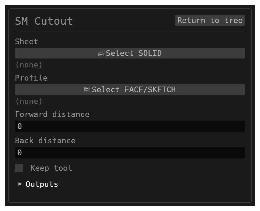
Sheet Metal Cutout removes a sketch profile from an existing sheet-metal body. The cut survives later flanges, hems, cutouts and unfolds, and shows in the flat pattern.
Inputs
id–string, defaultnull. Optional identifier for the history entry.sheet– singlereference_selection(SOLID, defaultnull). Target sheet-metal solid; when omitted, the sole sheet-metal body resolves automatically.profile– singlereference_selection(FACE,SKETCHorSOLID, defaultnull). Sketch profile to cut with (a sketch or its display face), or a solid body used as the cutting tool. The sketch is always consumed on success. Each sketch region cuts independently; a region's inner loops are islands whose material stays. A face of a solid as the cutter is refused.forwardDistance/backDistance–number, each default0. Blind cut depths measured from the sketch plane along +/− the sketch normal.0cuts through everything on that side, so the default is a through-all cutout. A solid tool ignores them.keepTool–boolean, defaultfalse. Also keeps the generated cutter solid(s) in the scene ({id}:CUTTER, or{id}:CUTTER:{regionKey}per region). With a solid tool it keeps that solid; otherwise the tool is consumed.
Behaviour
- Rational profile curves stay exact: a circle cuts a true cylindrical bore.
- One region may cut several parallel flats (e.g. both plies under a 180° hem).
- A loop may overhang a plain outline edge (an edge notch).
- A cutout after a flanged hole builds, and the hole's collar survives the re-evaluation.
- Oblique cuts through non-parallel flats are supported when their angle is manufacturable; the resulting perpendicular-walled hole uses the union of the entry and exit footprints.
- A solid tool cuts every flat it passes through. On each flat the cutout takes the outline of the tool where it crosses the top face and where it crosses the bottom face, and cuts the union of the two straight through, with walls perpendicular to the sheet. A tool set at an angle therefore gets an opening larger than either outline, one it can be pushed straight through, as on a laser-cut part. A tool that bulges inside the thickness (a sphere centred in the sheet) is cut to its face outlines only. A tool that ends inside the sheet, or misses it, is refused.
- Refused rather than cut wrongly: a loop crossing a bend arc, a near-tangent oblique tool, or a region that lands on no flat all abort with a specific message. One known gap: a tool that threads a bend arc while missing both flats beside it, and cuts some other flat, can get past these checks.
Walkthrough
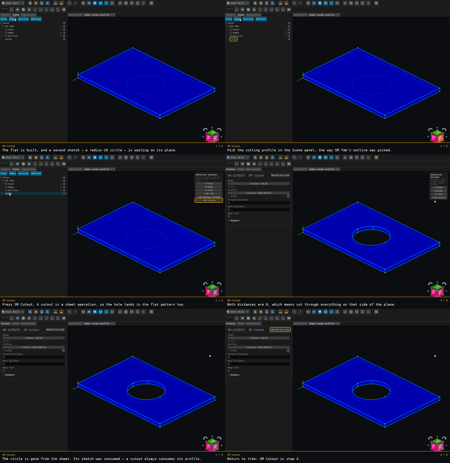
Recorded from the running app by BREP_mcp/tests/videos/sheet-metal-cutout.json; regenerate every walkthrough with ./build.sh docs-videos.
The fixture carries two sketches on the same plane: the rectangle the flat is seeded from off camera, and the radius-10 circle the walkthrough cuts with. The cutting profile is picked in the Scene panel for the same reason SM Tab's outline is.
sheet is left empty on purpose — it auto-resolves when the part holds exactly one
sheet-metal body. The result is arithmetic: 4800 − π × 10² × 2 = 4171.681 mm³.