Sketch
Status: Implemented
Sketch owns a plane, a set of 2D geometry and constraints, and a solver. On every regenerate it solves that geometry and publishes the result under its own name, where Extrude, Revolve, Sweep, Loft, Hole and the sheet-metal features pick it up. It produces no solid of its own.
Walkthrough
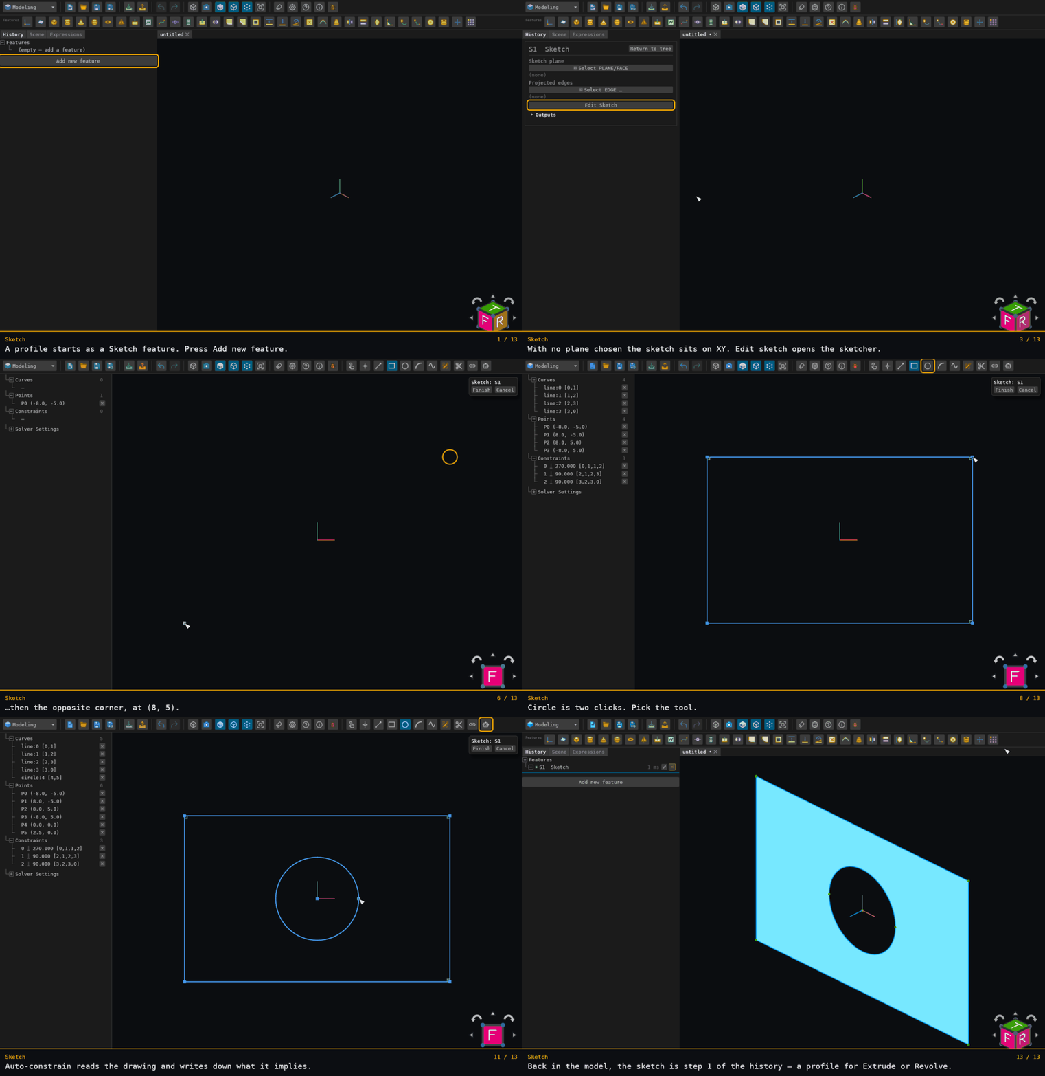
Recorded from the running app by BREP_mcp/tests/videos/sketch.json; regenerate every walkthrough with ./build.sh docs-videos.
Inputs
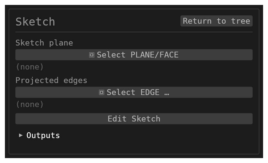
id–string, defaultnull. Every name the sketch publishes is prefixed with it.sketchPlane– singlereference_selection(PLANEorFACE, defaultnull). It is resolved on every regenerate, so the sketch follows its reference when the reference moves. A sketch cannot use its own profile face as its plane.projectedEdges– multiplereference_selection(EDGE, defaultnull). The list of the sketch's linked model edges: each is projected onto the sketch plane as read-only reference geometry and appears in the editor as linked construction geometry; edges linked with the editor tool are written here (see Referencing model geometry).editSketch–button, defaultnull, that opens the 2D sketch editor.
The geometry, constraints and plane basis are not dialog fields; they are edited in the sketch editor.
Entering and leaving sketch mode
Edit Sketch opens the editor in the 3D viewport. The model rolls back to the step
before the sketch, so the backdrop is the model as it stands underneath this
feature, the camera swings to face the sketch plane, and the 3D selection is cleared.
Finish and Cancel live in the shared top-right mode-exit card. Finish writes
the sketch, its dimension-label offsets and its external-edge links back into the
feature. Cancel discards the session's changes; it does not remove the feature, so
a sketch added and then cancelled stays in the history, empty. Either way the
previous rollback and camera are restored.
While a sketch is open:
- The main toolbar row holds the drawing tools and auto-constrain (see Drawing tools).
- The left panel lists the sketch's Curves, Points and Constraints. A row click
selects (following the Multi-select setting, as in the viewport), hovering a row
highlights that entity.
toggles its row into the selection and deletes the selection: under the defaultClick togglesanything else selected goes with it, and on a row that is already selected it deletes the others and keeps that row — so clear the selection first. Solver Settings sits at the bottom of the panel, collapsed by default. - The bottom status bar shows the sketch id, the degrees-of-freedom readout, the
selection count, and the
Lock to sketchtoggle. - The top-right card shows the actions that apply to the current selection.
- Undo/redo are the main toolbar's buttons (and Ctrl+Z / Ctrl+Y or Ctrl+Shift+Z). While a sketch is open they drive the sketch's own edit history rather than the feature history.
Lock to sketch is on by default: it holds the view flat to the plane and reserves
the left mouse button for sketching, so left-drag never moves the camera. Pan stays
on the right and middle buttons and the wheel still zooms. Unchecking it frees
orbiting; re-checking snaps the camera back flat to the plane.
Text outlines
Choose Text in the sketch toolbar and place two opposite corners. The text object has four construction edges. Dimension or constrain these edges to set its position, rotation, width, and height; the text fits the rectangle.
Select the letter outlines (or the text row in Curves), then choose Edit text in the selection toolbar. The dialog changes only Text and Font. Apply accepts the edit; Cancel leaves the object unchanged. Ubuntu Light and Hack Regular are bundled. Text is a single line, up to 256 characters; unsupported characters are reported instead of substituted.
Glyph contours are closed cubic outlines, including the holes in letters such as B and O. Finish the sketch and use it as an extrusion profile. The outlines are saved in the document, so reopening it does not depend on installed fonts. Glyph points and segments are not individually editable or constrainable. Deleting the text or one of its boundary edges removes the whole text frame; undo restores it.
Mouse and keyboard
| Input | Action |
|---|---|
| Left click | Place, with a draw tool armed; otherwise select. Under the default Multi-select setting (Click toggles) each click adds or removes an entity and a click on empty space clears; under Ctrl+Click a plain click replaces the selection and Ctrl/Cmd adds. |
| Left drag on an entity | Move a point, or translate a whole curve. |
| Right click, mid-draw | Abort the geometry in progress. The tool stays armed. |
| Right / middle drag | Pan. Wheel zooms toward the cursor. |
| Double-click a dimension | Edit its value in place. |
| Drag a dimension label | Reposition the label. |
Esc | Drop the active tool back to Select — this is also what ends a run of line segments. |
Del / Backspace | Delete the selection. |
Ctrl/Cmd+Z, Ctrl/Cmd+Y | Undo / redo the sketch edit. |
Deleting is transitive: removing a point also removes the curves that used it and the constraints that referenced it. Every delete — even of a single constraint — also sweeps up every point in the sketch that no surviving curve uses, including standalone points placed with the Point tool (such as a Hole placement sketch's).
Degrees of freedom
The status bar reports the solve state as a coloured dot. The first state that applies is the one you see:
| Colour | Meaning |
|---|---|
| Red | Conflicting constraints, with the number implicated. |
| Yellow | Over-constrained, with the redundant-constraint count, and the remaining degrees of freedom if any are left. |
| Blue | Under-constrained, with the remaining degree-of-freedom count. |
| Green | Fully constrained. |
Red never shows a degree-of-freedom count. Conflict and freedom are not alternatives — a sketch can be unsatisfiable and under-constrained at the same time — so read a missing number there as "not shown", not as "none".
A sketch does not need to be fully constrained to be used — an under-constrained sketch extrudes exactly as drawn. The readout is guidance, not a gate.
When constraints conflict
The dot turns red when the solve came to rest with constraints it could not satisfy. The constraints need not over-determine anything: two lines from a shared corner, each tangent to the same circle, dimensioned 20 and 13, are impossible — two tangent lengths from one point are equal — yet nothing is redundant, and it is flagged. A sketch the solver fails to converge on reads the same way. The exception is a sketch with more than 600 free points, which gets no final polish (see Solver settings): there a constraint is flagged only if it is also redundant, so an impossible or non-converged sketch of that size can stay un-flagged.
The conflicting constraints are shown in the same red — their glyphs and dimension leaders, the dimension values, and their rows in the Constraints list:
- Where the constraints are mutually dependent, the red set is the group whose effects cancel exactly — all the ones that cannot hold together, not just whichever the solve happened to leave most violated.
- Otherwise — the impossible sketch above, or one that failed to converge — the red set is the constraints the solve could not satisfy. That is neither complete nor minimal: it can include one pulled out of place by the compromise, and miss one in the causal chain that happens to be satisfied where the solve stopped.
Treat the red set as where to look, not as a list to delete from. A constraint the
solve can satisfy stays green even while the sketch conflicts. The red is the
Conflicting constraint colour under Sketch in the display settings.
Drawing tools
The tools sit at the end of the main toolbar row, after the active workbench's buttons. They belong to no workbench — every workbench carries them — and they are offered exactly while a sketch is being edited, so switching workbench mid-sketch keeps them.
One tool is armed at a time and draws pressed; pressing the lit one puts it down
(back to Select). Select is the no-tool state.

The row above is the toolbar under Modeling with a sketch open and the Circle tool armed.
| Button | Id | Offered | What it does |
|---|---|---|---|
| Select | sketch.tool.select | while a sketch is being edited | Select and drag points and curves. |
| Point | sketch.tool.point | while a sketch is being edited | Place a point on the sketch plane. |
| Line | sketch.tool.line | while a sketch is being edited | Draw connected line segments; each click starts the next segment, Esc ends the run. |
| Rectangle | sketch.tool.rect | while a sketch is being edited | Draw a rectangle from two opposite corners. |
| Circle | sketch.tool.circle | while a sketch is being edited | Draw a circle from its centre, then a radius point. |
| Arc | sketch.tool.arc | while a sketch is being edited | Draw an arc from centre, then start, then end. |
| Bezier | sketch.tool.bezier | while a sketch is being edited | Draw a cubic Bezier: end, control, control, end. With nothing half-drawn, a click on an existing spline adds a point to it. |
| Freehand | sketch.tool.handdraw | while a sketch is being edited | Draw a stroke; on release it is fitted to clean geometry. |
| Trim | sketch.tool.trim | while a sketch is being edited | Trim a curve at the nearest intersections around the click. |
| Link edge | sketch.tool.pickEdges | while a sketch is being edited | Pick a model edge and bring it into the sketch as fixed construction geometry. |
| Text | sketch.tool.text | while a sketch is being edited | Places text outlines inside a constrainable construction rectangle; select the text to edit its contents and font |
| Auto-constrain | sketch.autoconstrain | while a sketch is being edited | Add the constraints the rough-in geometry implies (see Auto-constrain). It is an action, not a tool. |
How many clicks of the armed tool are buffered shows in the bottom status bar as
… N placed, beside the selection count.
Drawing a rectangle also adds three perpendicular constraints, so the rectangle stays rectangular when you drag a corner.
Snapping and inferred constraints
One radius governs every pick in the sketcher: about 12 screen pixels, converted to sketch units at the current zoom. It is not adjustable — zoom in for finer control.
Two different things happen inside that radius:
- While drawing, clicking within the radius of an existing point reuses that point rather than creating a second one on top of it. The curves share one point, so no coincident constraint is added.
- When you finish dragging a single point, the sketcher infers a constraint from where you dropped it: a coincident constraint to the nearest point within the radius, or failing that a point-on-line constraint to the nearest line — promoted to coincident if you landed on one of that line's endpoints. Dragging a whole curve infers nothing.
Auto-constrain
The auto-constrain button reads the whole sketch and adds only two kinds of constraint:
- Horizontal or vertical on any line lying within 3° of an axis.
- Coincident between point pairs closer together than 1% of the sketch's bounding diagonal (never less than 0.0001).
It skips lines already carrying a horizontal or vertical constraint, points already transitively coincident, points of the same curve, lines fixed at both ends, and pairs of points that are both fixed — so running it twice adds nothing the second time. It does not stay armed.
Constraints
Applying one
Select geometry or points first; the top-right card then offers only the constraints that apply to that selection. With nothing selected the card is hidden. Most selections resolve to exactly one case:
| Selection | Offered |
|---|---|
| One arc or circle | Radius, Diameter |
| Two lines | Parallel, Perpendicular, Angle, Equal distance, Collinear, Point on line |
| Two lines, at least one a spline handle guide | The same, plus Tangent |
| The two handle guides either side of one spline anchor, or two spline end guides whose ends are joined | The same, plus Curvature (G2) |
| Two arcs/circles | Equal radius, Concentric, Tangent |
| One line + one arc/circle | Tangent |
| A spline end's handle guide + one arc/circle | Tangent, Curvature (G2) |
| A spline itself + one line, or a spline itself + one arc/circle | Tangent (span point) |
| One line + two points | Perpendicular, Symmetric about line (plus the point cases below) |
Otherwise the offer is driven by how many distinct points the selection covers — selected points plus the endpoints of any selected curve (an arc contributes its centre and start only):
| Points covered | Offered |
|---|---|
| 1 | Ground |
| 2 | Horizontal, Vertical, Coincident, Distance |
| 3 | Midpoint, Point on line, Line-to-point distance, Angle, and Collinear when at least three points were selected individually |
| 4 or more, points only | Collinear |
Angle is offered for three points but adds nothing there; select two lines to dimension an angle.
Because a single selected line covers two points, selecting one line offers the two-point set — which is how you make one line horizontal or dimension its length.
The same card also carries Fix/Unfix (ground toggle, shown when points are
selected), Construction toggle, Angle measure (shown when exactly one angle
constraint is selected), Clean and Delete.
Changing how an angle is measured
Two lines meet at four sectors, and an angle constraint dimensions one of them.
Which one is set by the order the lines were picked, so the reading you get
may be the 167° outside the corner when you wanted the 13° inside it. Select
the angle constraint (its row in the Constraints list, or its dimension in the
view) and press Angle measure on the card: the dimension steps to the next
sector round the intersection and its value becomes the supplement
(180 − value), so 167° reads 13°, then 167° on the far side, then 13°, and
back where it started after four presses. Nothing moves; the constraint still
describes the same geometry, it just states it the other way, and the chosen
measure is saved with the sketch. A reflex reading (over 180°) first comes
back to the short way round the same sector (360 − value), then steps as
above. An expression-driven angle keeps its expression, wrapped as
180 - (…). Type a value over 180° into the dimension if you want the reflex
angle itself.
The constraint set
Each constraint's glyph is what you see on the card button and in the Constraints list.
| Glyph | Constraint | What it does |
|---|---|---|
| Ground | Locks a point in place. Linked external geometry is grounded this way. | |
| Horizontal | Forces two points to share the same y. | |
| Vertical | Forces two points to share the same x. | |
| Coincident | Merges two points onto the same coordinates. | |
| Distance | A numeric point-to-point dimension; also carries radius and diameter dimensions. | |
| Line to point distance | A perpendicular distance dimension from a point to a line. | |
| Equal distance | Makes two segment lengths equal. | |
| Parallel | Keeps two lines in the same direction. | |
| Perpendicular | Enforces 90° between two lines. | |
| Angle | An explicit angle between two segments, seeded from the current geometry. Angle measure on the card switches which of the four sectors between the lines it dimensions. | |
| Point on line | Holds a point on the line through two other points. | |
| Midpoint | Centres the third point between the first two. | |
| Tangent | Holds a line tangent to a circle/arc, or two circles/arcs tangent to each other. Splines are supported. | |
| ϰ | Curvature (G2) | Makes a spline curvature continuous across one of its joints, with a circle/arc at one of its ends, or with another spline's end. It includes the tangency, so it replaces Tangent on the same pair rather than joining it — a sketch carrying both reads as over-constrained by one. |
| Tangent (span point) | Makes a spline touch a line or an arc/circle somewhere ALONG the curve, rather than at one of its anchors. The touch point moves with the sketch; it is not a point you place. | |
| Concentric | Makes two circles/arcs share a centre. | |
| Equal radius | Makes two radii equal. | |
| Collinear | Holds three or more points, or the endpoints of two or more lines, on one line. | |
| Symmetric | Mirrors two points about a line. |
Tangency is solved as tangency, including against splines — not as a perpendicular constraint on a radius. (equal distance, two lines) and (equal radius, two circles or arcs) are separate constraints.
Curvature is offered where there is one joint to state it across: the two dashed handle guides either side of a spline anchor, two spline ends the sketch already holds together (a coincident, or the same point), or a spline end's guide and an arc/circle. It is not offered against a plain line, whose curvature is zero.
The two spline tangencies are told apart by WHAT YOU SELECT. Pick a spline's dashed handle guide and you ask for tangency at that anchor (). Pick the spline itself and you ask for it somewhere along the curve () — the touch point is found for you and slides as the sketch changes. needs a touch point to exist: if the line's direction is one the curve's tangent never takes, the constraint says so instead of guessing, and moving or turning the line gives it something to hold. It also says so when the touch point lands exactly where the curve changes which way it bends.
Adding a constraint that already exists on the same points is a no-op: constraints are de-duplicated on type plus point set.
Dimensions and expressions
Distance, Radius, Diameter, Angle and Line-to-point distance are dimensional: they carry a value, seeded from the geometry's current measurement, and show it as a label in the viewport. Double-click a label to edit the value in place; Enter applies, Esc cancels. Dragging a label repositions it, and the offset is stored with the sketch.
A dimension can hold an expression instead of a number. Anything that is not a
plain numeric literal is evaluated against the same environment as the
Expressions panel and the configurator, so a dimension
written as width/2 tracks width. If the expression does not evaluate, the edit
is rejected and the previous value is kept. The editor has no way to type an
expression into a point coordinate; a coordinate written as an expression in the
document is evaluated on regenerate, and one that does not evaluate fails the sketch.
Radius and Diameter are both stored as a distance between the centre and a boundary point, differing only in display: a diameter dimension shows and accepts the doubled value, so a diameter driven by an expression is halved on the way in and doubled on the way out. Lengths display to three decimals and angles to one; the precision is fixed.
Trim
Trim removes the clicked span of a curve, bounded by the nearest intersections around the cursor.
- Lines, arcs, circles and Bezier splines can be trimmed.
- It splits at the nearest intersections bracketing the click, not at every intersection along the curve.
- A circle or full arc keeps the span opposite the clicked one.
- If no valid trim bounds exist — a curve exactly on top of another, or an endpoint already sitting on one — Trim removes the curve entirely. A curve that only partly overlaps another is split at the other's endpoints.
- Trimming against a line constrains the new point onto the cutting line (coincident when it lands on that line's endpoint); against an arc or circle the new point gets an equal-distance constraint from the centre so the radius survives. Splines trim without adding constraints.
- Points left referenced by nothing after a trim are removed automatically.
- Clicking a point with Trim armed deletes that point, along with whatever depended on it — the point takes priority over any curve under the cursor.
Splines
The Bezier tool creates one cubic Bezier from four picks: end, control, control, end. It also adds a dashed construction line from each endpoint to its neighbouring handle, so the handles can be positioned with ordinary sketch constraints — a tangent constraint on a handle guide is the usual way to make a spline meet a line smoothly.
With the Bezier tool armed and nothing half-drawn, clicking along an existing spline adds a point to it there: the span is split in two at that spot and the curve does not move at all. The new point is an ordinary sketch point, free to drag and to constrain, and it gets the same dashed guides to its two neighbouring handles that a drawn endpoint gets. A tangent constraint on either guide holds the curve's tangent at the added point: the handle turns, and the point's other handle follows so the curve stays smooth through it.
Only splines respond to that click. Clicking a line, arc or circle — or empty space — starts a new spline, and so does every click while a spline is half-drawn, so a new spline can still be drawn across an old one. Clicking one of the existing control points does not add a point either: points take priority over curves everywhere in the sketcher.
Adding a point keeps constraints already hung on the curve: the two end points are untouched, and the two handles either side of the click stay the same points — they only slide along their own tangent directions. The result is a multi-span Bezier; Trim produces the same when it splits a spline internally. To carry on past a spline's end instead, start the next one at its endpoint.
Freehand
The freehand tool captures a stroke and fits it to one clean primitive on release:
- a line, when the stroke is open and every sample stays within about 2% of the stroke's size of the straight chord;
- a circle when the stroke closes on itself and a least-squares circle fits within about 8%, or an arc when it fits that well but stays open;
- otherwise a single cubic Bezier through the endpoints, with its construction guides.
Stroke endpoints reuse nearby existing points, on the same pick radius and with the same no-constraint semantics as the draw tools. A stroke that is too short or too small — under three samples, or smaller than the pick radius — is discarded.
Construction geometry
Any point or curve can be toggled to construction from the context card. Construction curves constrain but never model: they are skipped when the profile is built, so they cannot become a profile edge or a hole boundary, even when they close a loop.
Every line in the sketch, construction included, is also published as a named axis, which is what makes a construction centreline usable as a Revolve axis.
Referencing model geometry
The part origin. Every sketch carries the part's (0, 0, 0) projected onto its
plane as a reference point, listed as Origin in the Points list. It is fixed,
grounded, construction and an external reference, so clicking on it while drawing
reuses it and any point can be constrained to it. It cannot be deleted, un-grounded
or turned into regular geometry. It exists only inside the sketch: it is never drawn in 3D,
never published as a scene point (so a Hole never drills there), and never becomes
profile geometry. Unlike linked edges it follows the plane on every regenerate — if
the sketch plane moves, the origin is re-projected before the sketch solves.
Linked model edges. A model edge is linked into the sketch in either of two
places, and both write the same list: the projectedEdges field of the sketch
feature, and the Link external edge tool inside the editor. An edge picked
in the editor appears in the feature's projectedEdges list when you Finish; an
edge added to that list from the dialog appears in the editor as a linked edge the
next time the sketch is opened. Removing an entry from the list unlinks it.
A linked edge does two things:
- In the model. The kernel projects it onto the sketch plane on every
regenerate and publishes it as a read-only reference path named
{sketchId}:REF:{edge name}. Resolution is live, so the path follows the source edge — including edges of a placed component when it is re-posed. These are not sketch curves: they cannot be dragged or constrained, and do not contribute to the profile. - In the editor. The whole edge is projected into the sketch as real construction geometry, classified by shape: a straight edge becomes a line, a circular one a circle or arc, and anything else a chain of line segments following the projected curve. Every point it creates is fixed, grounded and marked as an external reference, and the curve itself is construction — so it never becomes a profile edge, but you can draw to it, snap to it and constrain against it. The arc direction is normalized so the sketch arc covers the edge, never its complement.
Linked geometry is re-projected when the sketch is re-opened, not on every regenerate. If the model moves underneath, the stored coordinates stay put until you open the sketch again, at which point every still-resolvable link refreshes. The reference path, by contrast, always tracks the model.
When a linked edge disappears. If the feature the edge came from is deleted,
or a regeneration no longer produces that edge, the link is released rather than
dropped: the line, arc or circle stays in the sketch at its last coordinates as
ordinary construction geometry with fixed, grounded points — a real sketch entity
you own, which you can un-ground, move, delete or turn into regular geometry.
The entry leaves the projectedEdges list and the feature reports nothing
unresolved. Undoing the deletion restores the link. The same release happens on
the next open when you remove an entry from the list yourself. A list entry that
never resolved (one added for an edge the sketch cannot see) stays listed and is
reported as unresolved, since there is no geometry to keep.
To drop a link together with its geometry, select its points or curve in the sketch and delete them; the entry leaves the list on Finish, which frees that edge to be linked again. Documents saved before the list and the editor tool were unified open unchanged; their links join the list on the first Finish.
Solver settings
Solver Settings is collapsed at the bottom of the left panel and holds two knobs
plus Reset to defaults:
- Max iterations – the relaxation iteration cap, default
1000. - Override tolerance – off by default; when enabled it replaces the solver's
convergence tolerance (default
1e-5, seeded at1e-6when you switch the override on).
Changing either re-solves immediately. These settings govern the solve in the editor; the regenerate solve always uses 2000 iterations and the default tolerance.
Every solve, including interactive drag frames, runs a Levenberg-Marquardt polish after the iterative pass, so the geometry that reaches the kernel is exact rather than sitting at the relaxation floor. A sketch with more than 600 free points (grounded points and linked-edge points do not count) skips the polish, and its geometry stays at that floor.
There is no "solve continuously" mode and no orphan-point setting. Trim sweeps up
points nothing refers to, and Delete every point no curve uses; the Clean action
removes every point that no geometry and no constraint refers to, so a point held
by even a single constraint survives it.
From sketch to profile
On every regenerate the sketch solves, then turns its solved geometry into named scene entries:
- Chaining. Non-construction lines, arcs and Beziers are chained into maximal
runs by coincident endpoints (tolerance
1e-5mm). Circles and ellipses are closed loops on their own. A branching junction ends a run; the other branch starts its own. - Loops and regions. Closed runs become profile loops, grouped into disjoint regions by even-odd containment: a loop at even nesting depth is a region's outer boundary, a loop at odd depth is a hole in the region that directly contains it — so an island drawn inside a hole becomes solid material in its own region. One sketch can drive several disjoint solids at once.
- Path. Open runs become the sketch's path. The longest open run wins, so a sweep trajectory can be drawn alongside a profile in the same sketch. With no open geometry, a single closed chain of lines, arcs or Beziers doubles as the path; a circle or ellipse never does.
- Publishing. The profile, the path and the resolved plane frame publish under
the sketch's own id. Each model curve also publishes as its own path
{id}:G{gid}, each line as an axis under the same name, each solved point as{id}:P{pid}, and each projected edge as{id}:REF:{name}.
A sketch with no closed loop is not an error — an open, axis-only or empty sketch publishes its path, axes and points and simply has no profile.
A committed sketch draws in dim cyan and appears in the Scene tree until a downstream feature consumes it: a closed profile draws as a filled sheet, and every model segment the sheet does not cover — an open chain, a lone line, a sweep trajectory drawn beside a loop — draws as a named edge. So an open sketch is visible and clickable in the viewport too; it just has no face to click.
Referencing a sketch from another feature
| Feature | What it takes from the sketch |
|---|---|
| Extrude, Loft, Sheet Metal Tab, Sheet Metal Cutout | The profile. |
| Revolve | The profile, plus an axis — usually a construction centreline. |
| Sweep, Path Sweep | The profile, plus a path. |
| Sheet Metal Contour Flange | The path — the sketch's longest open chain, or its single closed loop when it has no open chain (a closed path is then refused). |
| Rib | The path. Its field is called profile, but it wants an open chain. |
| Tube | Individual curves, picked one at a time. |
| Hole | The sketch's points and its plane — one hole per point. |
| Pattern | An axis. |
How the reference is spelled
The same sketch can be referenced three ways, and all three resolve for a profile
field, Hole's included: the bare sketch id, {sketch}:FACE, and the older
{sketch}:PROFILE. {sketch}:FACE is what a viewport click stores, because a
committed sketch is drawn as a sheet whose single face carries that name; picking the
sketch in the scene tree or the context bar stores the bare id instead. The alias is
also understood by the change-tracking that decides which features must re-run when
you edit a sketch.
Hole drills every model point of the placement sketch and skips every construction point (the toggle, and the points a linked model edge materializes), so a placement sketch should carry only the points you want drilled. A sketch that holds only points is drawn as vertex markers on its plane, so it stays visible, listed in the scene tree and pickable in the viewport.
Per-curve references matter for branching sketches: a Y-junction has no single
ordered chain, so Tube resolves each picked sketch curve through its own
{id}:G{gid} name rather than through the one path.
Consuming the sketch
Extrude, Revolve, Sweep, Path Sweep, Loft and Rib carry
consumeProfileSketch, on by default: the sketch disappears from the scene and the
tree once the feature succeeds. Turn it off to keep the sketch visible and drive
more than one feature from it. The sheet-metal features have no such switch — they
always consume their sketch.
Consuming affects the display only. The sketch's published names stay resolvable, so a later feature can still use a consumed sketch's axis, path or points — which is what makes "extrude the profile, revolve about the centreline of the same sketch" work.
Face names and loop identity
Faces created by sweeping a profile are named from the sketch, so downstream selections survive a rebuild:
- Side walls are named from the source curve:
{feature}:{sketch}:G{gid}_SWfor Extrude and Sweep, and{sketch}:G{gid}with a suffix for the others (_RVrevolve,_LFloft,_SWPpath sweep). BecauseG{gid}is the sketch geometry's own id, a side wall keeps its name as long as that curve exists. - Caps embed the loop's stable id:
{cap base}:L{loopId}_STARTand_END. - Hole walls — the walls of an inner loop — are named
{feature}:HOLE:L{loopId}. Revolve instead names a hole's walls from its curves (_RV), like its outer walls.
A feature that builds the same wall SEVERAL times keys each one further and registers
the name above as the group standing for all of them. Sweep does this per
path segment: {feature}:{sketch}:G{gid}:{pathSegment}_SW and
{feature}:HOLE:L{loopId}:{pathSegment}, so a wall keeps its name when a different
part of the path is edited. A reference stored under the un-keyed group name still
resolves, and on a single-segment path it resolves to exactly the one face it named.
Each closed loop in a sketch owns an id that is persisted onto its member curves, so it survives editing the loop, and adding or removing a different loop does not rename this one's faces.
- A loop keeps its id when you add or remove edges from it — including the edge the id was originally seeded from.
- Splitting one loop into two keeps the original id on one half and mints a new one for the other; rejoining them restores the survivor's id.
- Ids are stamped into the sketch when you finish a sketch, and also when a document is loaded — so a model built by a script or an import gets them without ever opening the editor. Stamping renames nothing.
- A profile taken from a model face rather than a sketch has no loop id, so it keeps the older unkeyed cap names.
When a stored reference misses because of this naming, the error names the
replacement — an unresolved E4:S3:PROFILE_START[1] reports the
E4:S3:PROFILE:L9_START that supersedes it.
Limitations
Geometry
- The editor draws points, lines, rectangles, circles, arcs and cubic Beziers —
one span per Bezier invocation, with the tool's add-point and Trim producing
multi-span chains. The kernel additionally accepts
ellipsegeometry and will build profiles from it, but no tool creates an ellipse — it can only arrive in a document written by something else. - Any other geometry type in the sketch data is a hard error, not a silent skip.
- Zero-radius circles and arcs, zero-length ellipse axes, and a closed run of fewer than two edges are errors.
- Endpoints must meet within
1e-5mm to chain. Two curves that merely look joined will not close a loop; use a coincident constraint rather than eyeballing it.
Loops
- There is no self-intersection check. Crossing loops are caught only when they break the even-odd nesting — a figure-eight drawn as a single loop is not detected at all, and produces whatever the containment test makes of it. Keep profile loops simple and non-crossing.
- A sketch with no closed loop has no profile and therefore no sheet FACE to click in
the viewport. Its segments still draw and pick as edges (
{id}:G{gid}), and the scene tree always selects the sketch itself.
Editing
- No box or rubber-band select: build a multi-selection by clicking (see Mouse and keyboard) or from the entity lists.
Downstream
Some consumers are stricter than the sketch itself, so a profile that builds fine may still be refused:
Revolverejects a hole loop that touches or crosses the axis.Loftrequires every section to share the same region and loop structure — same region count, same holes per region, same curves per loop.Ribaccepts only an open straight-segment polyline; arcs and closed loops are refused.Sheet Metal Tabrefuses a profile with more than one disjoint region.Sheet Metal Contour Flangerequires an open, planar, head-to-tail path that starts and ends with a straight segment, has no two consecutive arcs, joins arcs tangentially, and has every arc radius greater than half the material thickness. Free-form spline segments are refused.