Plane
Status: Implemented
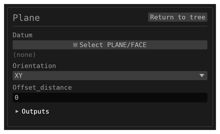
Plane creates a named construction plane for sketches and other references. It produces no solid: it registers one named frame (origin + normal) that later features resolve by name, drawn in the viewport as a soft-blue, selectable plane.
Walkthrough
Inputs
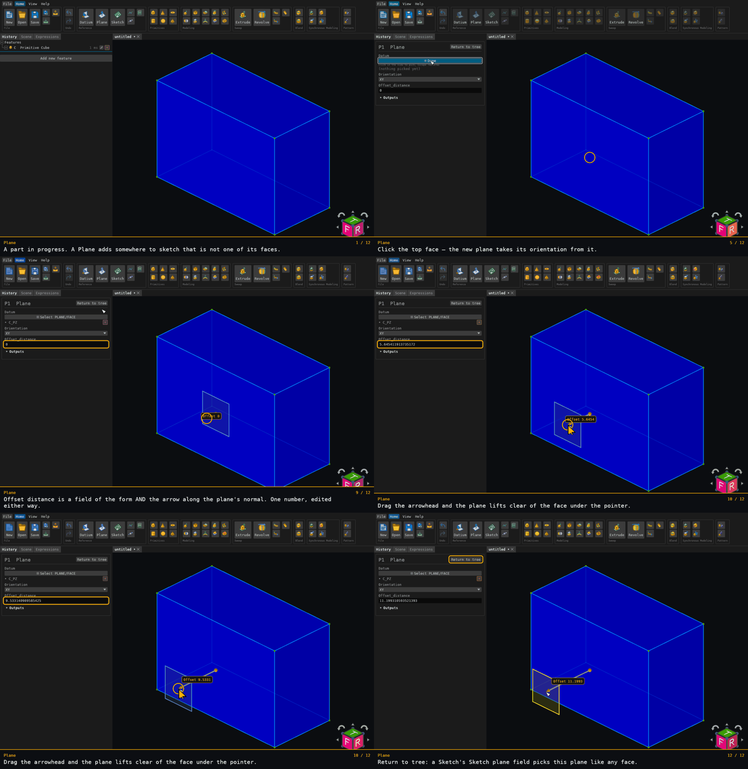
id(string, defaultnull) – identifier under which the frame is registered.orientation(options, defaultXY) – one of the world-aligned bases (XY,XZ,YZ). Used when nodatumreference is given.datum(reference_selection,PLANE/FACE, defaultnull,multiple: false) – an optional reference to an existing plane or planar face. When present it takes priority overorientation: the new plane inherits that reference's origin and normal.offset_distance(number, default0) – distance to shift the plane along its own normal.
Behaviour
- With no
datum, the plane passes through the origin.offset_distancethen moves it along the normal, and its in-plane axes are the ones a sketch derives when it references the plane. - The frame is registered under the feature's own id, so other features can pick it
through a
PLANEselection filter or by name. - If the
datumreference cannot be resolved (for example the referenced face was removed), the feature registers no frame and records the reference as unresolved rather than falling back to a world plane.
Notes
- The orientation normals are
XY→+Z,XZ→−Y,YZ→+X, so a positiveoffset_distanceon anXZplane moves it in−Y.
Frames for planar face references
A sketch or construction plane referencing a planar face uses its outward normal
as z. Its origin is the centre of the world-axis-aligned bounding box of the
face boundary samples, projected onto the face plane. Each non-degenerate
boundary edge contributes five equally spaced parameter samples, including its
endpoints; holes also contribute. This sampled extent defines the origin even
when a curved edge reaches farther between samples.
The in-plane axes follow the document's normal-based frame convention. With a
unit normal z, choose up = +Y, except when abs(z · +Y) > 0.9, where
up = +X. Then x = normalize(up × z) and y = normalize(z × x).
The reference's own in-plane axes do not determine these derived axes. Datum
plane references retain their registered origin and normal before this
normal-based convention supplies the sketch axes.