Drawing Workbench
Id: drawing · Seventh entry in the workbench dropdown
Drawing makes drawing sheets: paper with the model's saved PMI views placed on it, drawn with hidden lines removed and their annotations beside them, plus the drawing's own dimensions, ordinate runs, section views, detail views, a title block and a revision table. The views a sheet places are captured and annotated in the PMI workbench; this workbench reads them.
What it offers
Drawing creates no features. It adds the Sheets panel, the 2D sheet viewport that draws the open sheet, and the toolbar buttons below. Leaving for a workbench without the Sheets panel closes an open sheet; the sheet keeps its contents.
Toolbar buttons
Fourteen: Add sheet and Place view always, and twelve more while a sheet is open. The sheet viewport has no floating toolbar of its own.
| Button | Id | Offered | What it does |
|---|---|---|---|
| Add sheet | drawing.add_sheet | always | add a sheet at the default paper size and open it on the paper |
| Place view | drawing.place_view | always | place the first saved PMI view on the open sheet and open the placement's dialog, where the view, position and scale are chosen |
| Back to 3D | drawing.sheet_close | while a sheet is open | close the open sheet; the viewport draws the model again and the sheet keeps its contents |
| Horizontal | drawing.dim.horizontal | while a sheet is open | add a horizontal sheet dimension and open its dialog, where its two anchors are picked |
| Vertical | drawing.dim.vertical | while a sheet is open | a vertical one |
| Aligned | drawing.dim.aligned | while a sheet is open | the true distance between two anchors |
| Angular | drawing.dim.angular | while a sheet is open | the angle between two straight edges, as this view projects them |
| Radius | drawing.dim.radius | while a sheet is open | a projected circle's radius |
| Diameter | drawing.dim.diameter | while a sheet is open | its diameter |
| Horizontal ordinate set | drawing.ord.horizontal | while a sheet is open | add an ordinate set — a datum and a run of members reading their distance along the paper's x — and open its dialog |
| Vertical ordinate set | drawing.ord.vertical | while a sheet is open | the same, reading up the paper |
| Section view | drawing.section | while a sheet is open | add a section view and open its dialog, where its cutting line is picked on a placed view |
| BOM table | drawing.bom | while a sheet is open | insert the sheet's BOM table — one per sheet — and open the sheet's dialog, whose Tables section chooses its columns, position and column width |
| Detail view | drawing.detail | while a sheet is open | add a detail view and open its dialog, where its circle's centre and rim are picked on a placed view |
Zoom to fit on the main toolbar frames the whole paper while a sheet is open, and the wheel zooms the paper as it zooms the 3D view.
The workflow
A construction button creates the object on the open sheet with nothing picked yet and opens its dialog in
the Sheets panel. Until its references are picked the object is drawn as the reason instead
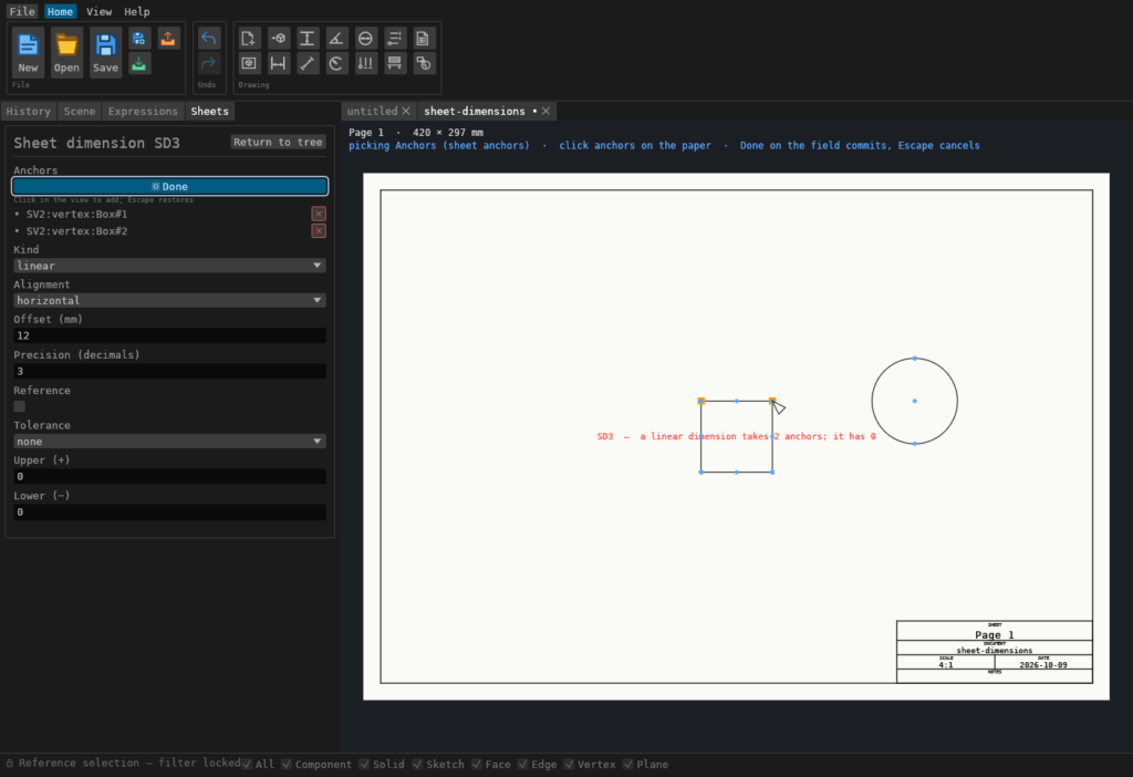
of a value — a dimension or ordinate set with its id in front (a linear dimension takes 2 anchors; it has 0), a section or detail on its own (no cutting line yet).
Each reference is a row of the dialog with a Select button, like a feature's references. Select opens the same reference picker every other dialog uses: the rest of the interface steps aside, every anchor of every placed view is marked on the paper, and each click on one adds it to the picker's list on the mode card (a pick already made is drawn larger, in orange). Finish writes the list into the row; Cancel — or Escape — leaves the row as it was. While picking, a drag on the paper pans it and nothing on the paper can be moved or opened, so a click always means "pick this anchor". Where a dimension's line or an ordinate set's baseline sits is a field of the same dialog, and a drag of its value box on the paper.
Anything on the paper has the menu of its row in the Sheets panel: right-click a view, a
dimension's value or an ordinate set's 0.000 to select it and open that menu (Edit …,
Remove …), or bare paper for the sheet's own. Delete removes the selected view,
dimension or ordinate set — never the sheet.
Drawing sheets
A sheet is a paper size and the saved views placed on it. Each placement names a view, a
position on the paper in millimetres and a scale in paper millimetres per model unit, and
draws that view's camera as an orthographic projection: the model as silhouette, crease,
tangent and boundary lines with the hidden ones removed — a fillet draws the two lines where it
meets its neighbours, while a face that is only split in two draws no line along the split —
plus every annotation of that view, laid out in
its own annotation plane and projected through the same camera. Each placement has a
Flatten text to sheet checkbox, on by default: on, every text run and every feature
control frame is turned flat on the paper, keeping where the projection put it; off, the text
is drawn as it lies in its plane — foreshortened, turned with the plane, and on a plane
edge-on to the view left on a line, which the drawing reports. Annotation text is sized on
the paper (12 pt is 12 pt at any scale) while the VALUE is the model's — a 10 mm feature
drawn at 4:1 still reads 10.000.
Dimensions on the sheet
Beside the annotations a placed view brings with it, a sheet carries its own dimensions. They are drawn on the paper and anchored to a placed view's projected geometry — a projected corner, an end or the midpoint of a projected edge, or the centre of a projected circular edge — so they measure the drawing rather than the 3D model's annotation planes.
An anchor names the geometry by model identity, never by where it landed on the paper, so a dimension follows what it measures: change the camera, the scale, where the view sits or the model itself and the dimension re-reads. An anchor whose geometry is gone after a model edit leaves the dimension in place, marked unresolved with the reason, rather than removing it.
One of the six dimension buttons the open sheet puts in the toolbar row adds one: press
horizontal, vertical, aligned, angular, radius or diameter, then in its dialog press
Select on Anchors, click the anchors it wants on the paper — two for a linear or an
angular dimension, one circle for a radius or diameter; picking past that replaces the oldest —
and press Finish. The line sits 12 mm from its anchors; change Offset or drag the
value. The value is the model measurement — for a
linear dimension the distance between the two anchors as the view projects them, so a
foreshortened edge reads its projected length; for a radius or diameter the circle's own — in
model units at any drawing scale. An angular dimension reads the angle between two
straight edges as this view projects them, which is what an orthographic drawing can honestly
say about them: a cube seen from a corner shows its right angles at 120.000°.
Ordinate sets and section views
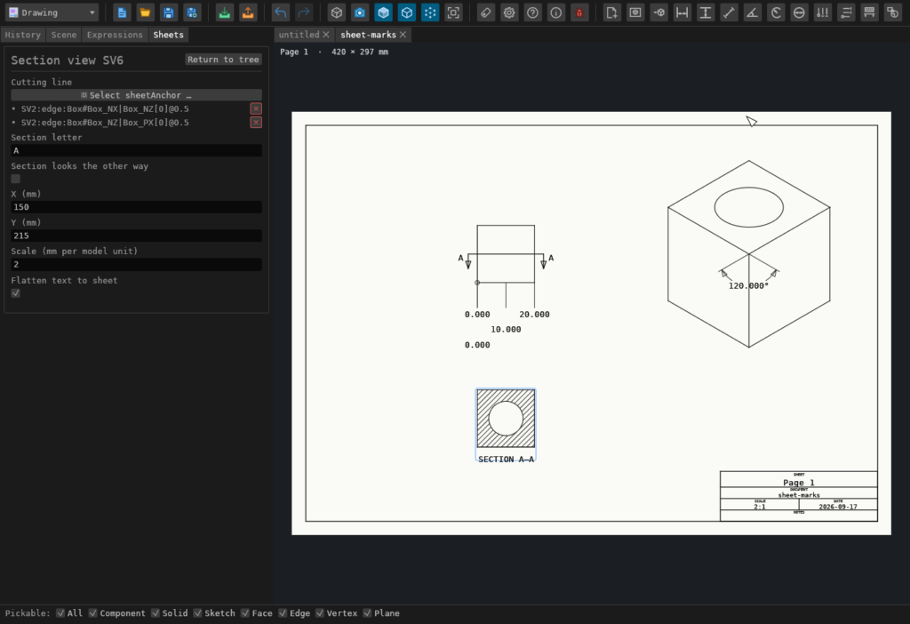
An ordinate set measures many points against one origin. Its dialog has two reference
rows: the Datum, one anchor, and the Members, any number — each a leader to the shared
baseline and its signed distance from the datum along one axis. The baseline sits 16 mm
from the datum; change Baseline offset or drag the datum's value. The datum is marked
with an origin circle and reads its own 0.000 at the baseline like every member, because a
run of distances with no visible origin cannot be read; a set whose datum is cleared stays, drawn as its id and the reason, until one
is picked again.
A section view cuts the model: in its dialog pick two anchors on one placed view as
its Cutting line. The first line picked names the view it is a section of; the section
takes that view's saved view and scale and is placed beside it (move it by dragging, or with
its X and Y). The cutting plane is the plane
through those two points containing that view's own viewing direction, the section looks along
its normal — to the side a reader walking from the first anchor to the second has on their
right — and the model is drawn clipped at the plane with its cut faces hatched. The line, its
arrows and its letter go on the view it was picked in; the section is captioned SECTION A—A.
Detail views, the revision table and the drawing set
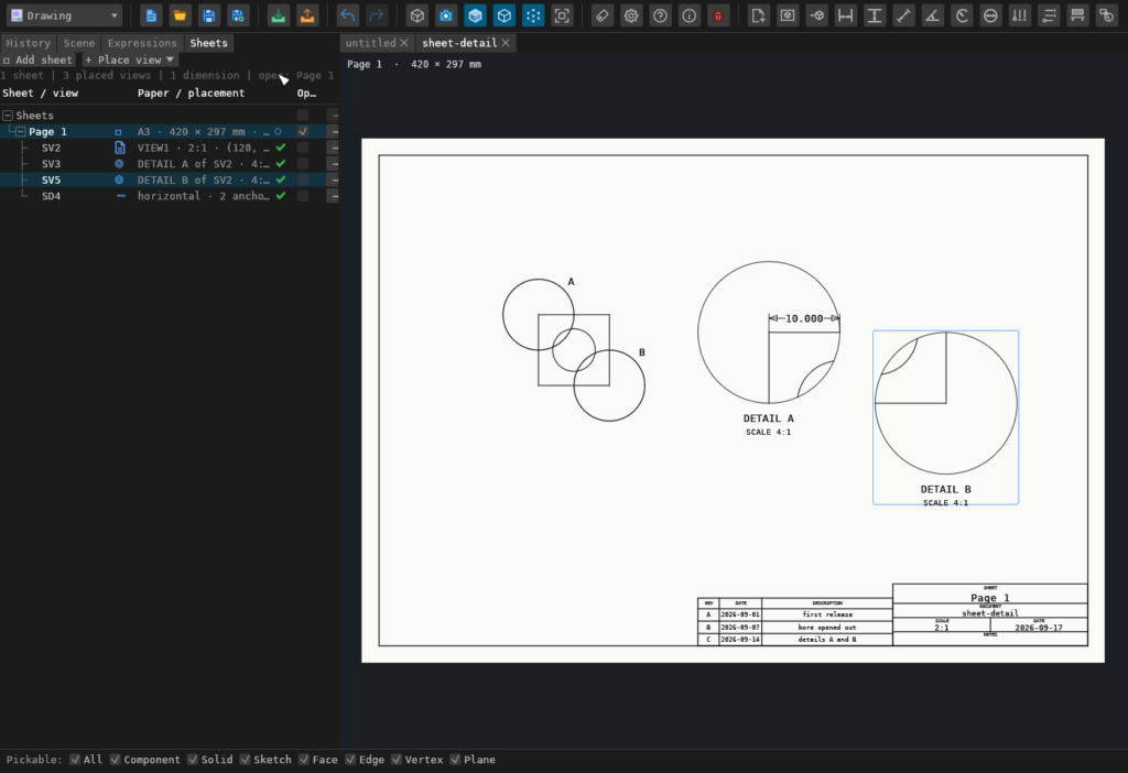
A detail view enlarges a region of a placed view: in its dialog pick an anchor as the
circle's Centre and one as a Point on the rim, both on the same view. The detail is
placed beside that view. The circle and its letter go on the view it was
picked on; the detail looks through that view's own camera at twice its scale (the placement's
Scale changes it) and draws only what is inside the circle, captioned DETAIL B over
SCALE 4:1. Which lines are hidden is worked out on the exact model inside the circle, so the
detail shows what its source shows, larger, and a hole seen end-on is one smooth arc at any
enlargement. Dimensions and ordinate
sets on a detail read the model — a 10 mm edge in a 4:1 detail reads 10.000. A detail or a
section of a detail or of a section is refused by name.
A sheet's revisions — a letter, a date and a description per line, edited in the sheet's dialog — are drawn as a table beside the title block, a header over the rows in the order they were added. A sheet with none draws no table.
Sheets (PDF), in the toolbar's Export… dialog, writes the whole document as ONE PDF: a page per sheet, in sheet order, each at its own paper size. The SVG stays one file per sheet.
Sheets live in the part file's sheets block, beside pmi; a document without a sheet
carries none. See the Sheets panel for the dialogs, the viewport
controls and the SVG and PDF output.