Sheets Panel
The Sheets panel lists the document's drawing sheets: one row per sheet, with the PMI views
placed on it as its children. It is a dock tab titled Sheets, shown only in the
Drawing and All workbenches. (The
PMI panel, where the views it places are saved, belongs to the
PMI workbench.)
A sheet is paper. It places saved PMI views — capture those in the PMI panel first — and draws each one as a projection of the model with hidden lines removed, together with every annotation of that view. It also carries marks of its own — dimensions, ordinate sets, section views and detail views — drawn on the paper and anchored to those projections, and a revision table beside its title block. It adds no geometry and changes no feature: opening, placing, dragging and dimensioning never rebuild the model.
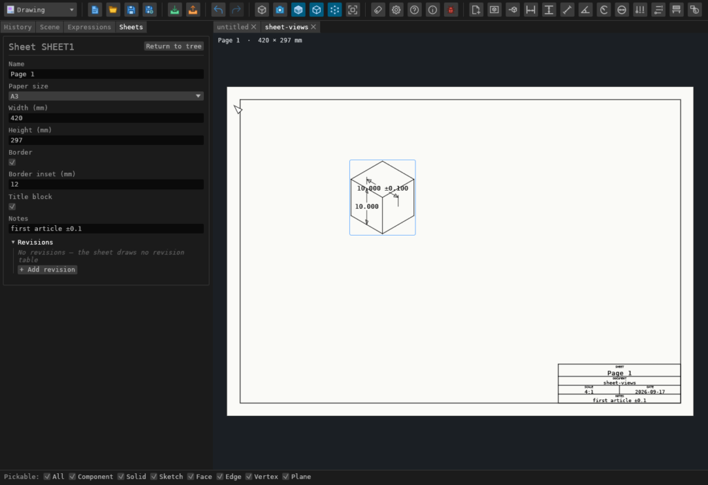
Header
- 🗋 Add sheet — a new A3 sheet (
Sheet N), opened in the sheet viewport. Its id (SHEET1, …) comes from one counter shared with the sheet's placements, dimensions and ordinate sets, so a second sheet made after a placement isSHEET3; ids are never reused. - + Place view — one entry per saved PMI view. Enabled once the document has both a sheet and a view; the new placement lands in the middle of the paper at 1:1 and its dialog opens.
- The summary
N sheets | M placed views | K dimensions | open: <name>, endingno sheet openwhile none is.
Rows
| Column | Sheet row | Placed view row | Sheet dimension row | Ordinate set row |
|---|---|---|---|---|
| Sheet / view | the name — edit in place to rename | the placement id (SV2, SV7, …) | the dimension id (SD3, …) | the set id (OD5, …) |
| (icon) | 🗋, blue while the sheet is open | , ◧ on a section view, on a detail view | ⋮ | |
| Paper / placement | A3 · 420 × 297 mm · 2 views | VIEW1 · 4:1 · (210, 149) mm · flat (or · projected); a section reads SECTION A—A of SV2 · 2:1 · (150, 215) mm and a detail DETAIL B of SV2 · 4:1 · (210, 149) mm | horizontal · 2 anchors · 10.000 ±0.050, with (from DIM1) when the tolerance is a PMI dimension's | horizontal · 3 members |
| (status) | on the open sheet | with the edge and annotation counts, with the reason it did not draw | with the value and the offset, with the reason it did not resolve | with the station count and the baseline offset, with the reasons its lost members give |
| Open | tick to draw the sheet in the viewport, untick to go back to the 3D model | — | — | — |
| Open / Close sheet, Edit sheet, Delete sheet | Edit placement, Remove from sheet | Edit dimension, Remove dimension | Edit ordinate set, Remove ordinate set |
A sheet's placements come first under it and its dimensions and ordinate sets after them — a
mark belongs to the paper, not to any one placement. Section and detail views are
placements and sit among them. Clicking a sheet row opens it in the sheet viewport; clicking
any other row selects it — the row is highlighted, and on the paper a dimension or ordinate set
is drawn in the accent colour while a placement gets an accent outline. Double-clicking any
row, a sheet's included, opens its dialog. The [+]/[-] box on a sheet row folds its children
away.
The menu is also the right-click menu, on the row and on the object on the paper.
Escape closes an open menu and leaves the
selection as it was; the next Escape clears it. Delete removes the selected placement,
dimension or ordinate set, as its menu's Remove entry does — one undo step. It never removes a
sheet, which takes everything placed on it with it; use Delete sheet for that.
The dialogs
Opening a sheet or a placement replaces the tree with its dialog. Editing is live and Return to tree closes the form.
Sheet — the name, the Paper size (A4, A3, A2, A1, A0, Letter, Tabloid,
or Custom with your own Width (mm) and Height (mm); a preset always draws at the
preset's size), and the paper's furniture:
- Border — the rectangle the drawing lives inside, and Border inset (mm), how far it sits from the page edge (10 mm by default). The title block is placed against the same margin, even with the border switched off. An inset that would leave no drawing area is refused rather than quietly shrunk.
- Title block — the stamp in the bottom-right corner, inside the border.
- Notes — free text, printed in the title block's last cell.
Border and title block are on by default, on every sheet, old ones included.
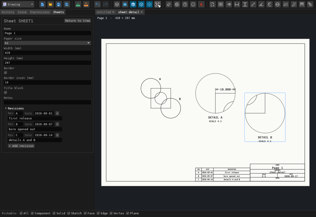
Revisions — the last section of the sheet's dialog: one line per revision, each a Rev
letter, a Date and a Description you type into, with a to remove the line, and
+ Add revision under them. A new line starts with the letter after the last one's (A on
an empty table, skipping I, O and Q) and today's date; change either by typing. The
lines keep the order you added them in, and the sheet draws them as its
revision table.
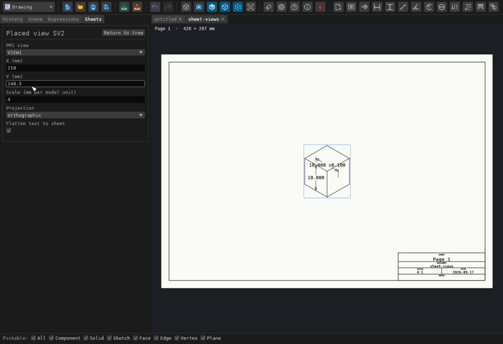
Placed view — which PMI view it draws, its X (mm) and Y (mm) position on
the paper (measured from the top-left corner, to the point the saved camera targets), and its
Scale (mm per model unit): 4 draws a 10 mm feature 40 mm long. Projection is
orthographic; a saved view with a perspective camera is refused rather than flattened.
Flatten text to sheet — on by default, per placed view: whether this view's annotation text lies flat on the paper or as it lies in its own annotation plane (see Flatten text to sheet).
Section view — X (mm), Y (mm), Scale (mm per model unit) and Flatten text to sheet, plus Cutting line (a reference row of two anchors), Section letter and Section looks the other way; see Section views. A section draws its source's saved view, so it has no PMI view or Projection field. A plain placement has none of the section fields, and a command that sets them on one is refused.
Detail view — the same four placement fields, plus Centre and Point on the rim (single-anchor reference rows) and Detail letter; like a section it has no PMI view or Projection field. See Detail views.
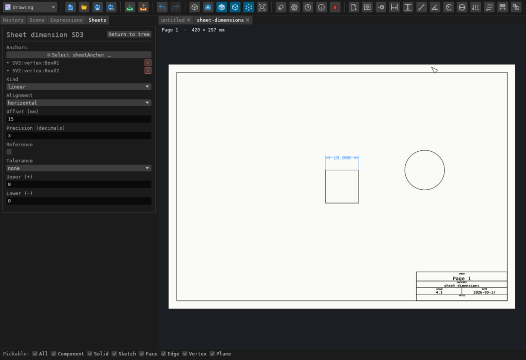
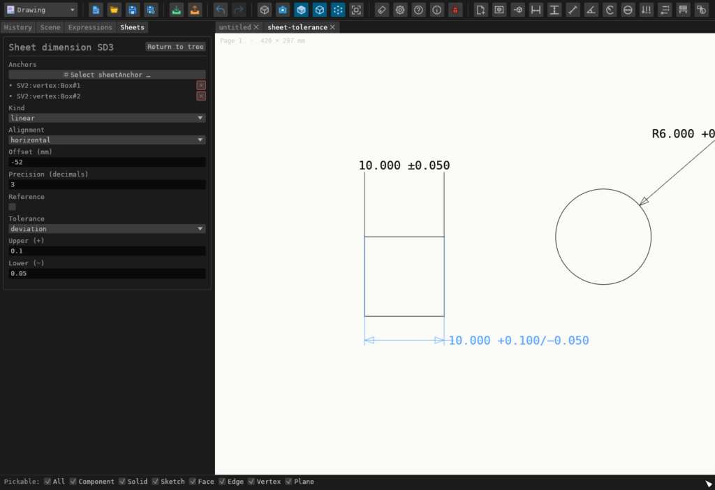
Sheet dimension — what it measures and how it is drawn. Kind is linear, radial,
diametral or angular; Alignment (a linear dimension's) is horizontal, vertical or
aligned. Anchors are reference rows like a feature's: two for a linear or an angular
dimension, one for a radius or a diameter, each naming a point of a placed view's projection.
Select opens the reference picker on the paper, seeded with these
anchors; Finish writes what it holds back into the rows. Offset (mm) is how far the
dimension line sits from its anchors, signed — on an angular dimension it is the arc's radius
from the corner; Precision (decimals) is how many decimals the value shows.
The last four fields are the dimension's tolerance block, the same four a PMI dimension's
dialog has: Reference (a reference dimension — the value in parentheses, no tolerance),
Tolerance (none, symmetric, deviation or limits), Upper (+) and Lower (−).
See Tolerances. When the value on the paper carries a PMI dimension's tolerance
instead of one of its own, the top of the dialog says which: Tolerance from PMI dimension DIM1: ….
Ordinate set — Axis (horizontal or vertical), a Datum reference row and a
Members list of them, Baseline offset (mm) for the shared baseline and Precision
(decimals). Dropping a member drops that one value; clearing the datum leaves the set
drawing its id and the reason, because every value was a distance from that point. Select on either
opens the reference picker: the datum holds one anchor, so a new pick
replaces it, and each anchor picked for Members is added to the list. The set's tolerance block — the same four fields
as a dimension's — is written on every member's value; the datum's 0.000 never carries
one, since it is the origin the others are measured from.
The sheet viewport
While a sheet is open the central 3D view draws that sheet instead: the paper with its border and title block, and each placed view's model lines and annotations.
There is no toolbar over the paper. The sheet's actions are buttons in the main toolbar's workbench row, offered while a sheet is open.
On the paper, with the pointer:
- Pan — drag on empty paper, or drag with the middle button.
- Zoom — the wheel, about the cursor, the same way it zooms the 3D view.
- Move a view — drag it. One undo step per drag, and the position is written to the document as you go.
- Edit a view — click it; its dialog opens in this panel.
- Move a dimension line — drag the dimension's value. One undo step per drag.
- Select a dimension — click its value; its row in this panel is highlighted and nothing opens. Edit a dimension — double-click its value; its dialog opens in this panel.
- Move an ordinate baseline — drag the datum's
0.000; the whole run follows. Click it to select the set, double-click it to open the set's dialog. - Right-click a view, a dimension's value or an ordinate set's
0.000— it is selected and its row'smenu opens. Right-click bare paper for the sheet's own menu (Close sheet, Edit sheet, Delete sheet). - Delete — removes the selected view, dimension or ordinate set, selected on the paper or in this panel; Ctrl+Z brings it back. Removing a view does not take the dimensions anchored to it: they stay, unresolved, naming the view they lost.
While the reference picker is up for a sheet object, the paper only pans, zooms and picks: nothing on it can be dragged or opened, so a click always means "pick this anchor".
On the toolbar:
- Zoom to fit — the toolbar's own fit button. While a sheet is open it frames the whole
paper instead of the 3D model; there is no second fit button, and no
+/−pair. - Add sheet and Place view — the first two buttons of the workbench row, always offered. Add sheet is the header's; Place view places the document's first saved PMI view on the open sheet and opens its dialog, where PMI view picks another.
- Back to 3D — the next button of the workbench row, offered while a sheet is open: the viewport goes back to the model and the sheet keeps its contents, as Close sheet and the Open tick do.
- The six dimension buttons, the two ordinate buttons, the section button and the detail button — one button per construction; see Dimensions on the sheet, Ordinate sets, Section views and Detail views. Each press adds its object to the open sheet with nothing picked yet and opens its dialog, where its references are picked. In a window too narrow for the whole row the row wraps onto further rows; there is no overflow menu.
Picking anchors
A sheet object's references — a dimension's Anchors, an ordinate set's Datum and Members, a section's Cutting line, a detail's Centre and Point on the rim — are reference rows in its dialog. Select on a row focuses it, the way a reference field in every other dialog is picked:
- the dialog stays in its pane with the row focused — an accent ring, its button reading Done — and the row lists the picks as they land. On a phone or a narrow window the whole interface steps aside instead and a bar over the paper lists the picks with Finish and Cancel (Picking references);
- the paper marks every point you can pick: a small square on each projected corner, a dot on each end and midpoint of a projected edge and on the centre of each projected circular edge; the anchors already picked are drawn larger, in orange;
- a click on a mark picks it — a corner wins over a point on an edge where both sit under the pointer. A single row holds one anchor, so a new pick replaces it; a list row adds each pick, and when it is full for its object (two for a linear or an angular dimension or a cutting line, one for a radius or a diameter) the oldest pick makes room. The beside a pick in the row drops it;
- a single row (a detail's Centre, an ordinate set's Datum) is written on its pick; a list row (Anchors, Members, Cutting line) is written when you press Done, press Select on another row, or close the dialog. Escape leaves the row as it was.
The object redraws as soon as the row is written. Until then an object without its references is drawn as its id and the reason, in the unresolved style.
Leaving the Drawing workbench for one without the Sheets panel closes an open sheet.
The title block
A fixed stamp against the bottom-right corner of the border, five cells, each a small label over its value:
| Cell | What it says |
|---|---|
| SHEET | the sheet's name |
| DOCUMENT | the open document's name, as the tab shows it |
| SCALE | the FIRST placed view's scale, as a ratio (4:1, 1:2) |
| DATE | the day the sheet was drawn or exported, UTC |
| NOTES | the sheet's Notes field |
A cell whose value is empty — an unsaved document, an empty note — is ruled but blank. The stamp is a fixed size, so it reads the same on an A4 and an A0; a sheet too small to carry it at full size scales the whole stamp down, and one smaller still gets none rather than an unreadable one.
The revision table
A sheet with revisions draws them as a table beside the title block — immediately to its left, at the same scale, its bottom on the same margin. The table is three columns, REV, DATE and DESCRIPTION, 110 mm wide in all; a header row 6 mm tall sits on top and each revision under it is a 7 mm row, in the order the dialog lists them. Text is level and centred in its cell: the header at the title block's label size, each row at 2.6 mm, as typed. A sheet with no revisions draws no table.
Where it sits, with the default 10 mm border inset (millimetres from the paper's top-left
corner; n is the number of revisions):
| Paper | Table x | Table bottom y | Table top y | Rows that fit |
|---|---|---|---|---|
| A4 (297 × 210) | 67 – 177 | 200 | 194 − 7n | 26 |
| A3 (420 × 297) | 190 – 300 | 287 | 281 − 7n | 38 |
| A2 (594 × 420) | 364 – 474 | 410 | 404 − 7n | 56 |
| A1 (841 × 594) | 611 – 721 | 584 | 578 − 7n | 81 |
| A0 (1189 × 841) | 959 – 1069 | 831 | 825 − 7n | 116 |
| Letter (279.4 × 215.9) | 49.4 – 159.4 | 205.9 | 199.9 − 7n | 27 |
| Tabloid (431.8 × 279.4) | 201.8 – 311.8 | 269.4 | 263.4 − 7n | 36 |
A Custom sheet too narrow for the table and the title block side by side stacks the table on top of the title block instead, right-aligned with it. With the title block switched off the table takes the title block's corner. A sheet too short for all its rows in any of those places draws no table — shorten the list, or use a larger paper. A description longer than its cell runs past the cell's rule rather than being cut.
What a view draws
The model as lines: every sharp edge and open boundary of the visible bodies, and the outline of every curved face — the two lines down the side of a cylinder or a cone, the circle round a sphere, the turning edge of a fillet or a torus — seen through that view's saved camera, with the lines behind a surface removed. A body the saved view hides is not drawn, and sketches are never drawn. Circles and arcs project as ellipses, as they do in any parallel projection — an annotation's arcs included. If the saved view explodes some bodies apart, the sheet draws them exploded, whichever view is active in the 3D viewport.
Then the annotations — all of them. Every enabled, resolved annotation of the saved view is drawn, seen through the same camera as the model: its dimension, extension and leader lines, its arrowheads, its feature control frames and datum symbols, laid out in that annotation's own plane and then projected. A plane oblique to the view draws foreshortened; a plane exactly edge-on to it projects to a line and is still drawn, not dropped. Annotations are drawn ON TOP of the model — they are not hidden by it, as in the 3D viewport.
Text and leaders appear as they do in the viewport, sized on the PAPER: a 12 pt annotation is
12 pt of paper at every scale, and the lines break around the value rather than running
through it. The value is not scaled. A 10 mm feature drawn at 4:1 still reads 10.000 —
the number is a measurement of the model, not of the drawing.
Flatten text to sheet
Flatten text to sheet, a checkbox on each placed view and on by default, makes annotations authored in a plane the view sees at an angle read left to right:
- On — every piece of text is turned flat on the paper, about its own anchor: it keeps where the projection put it and comes back to its full size, reading left to right. A feature control frame turns as ONE piece, frame and cells together, so its cells keep their order and their spacing, and a datum symbol's box and letter do the same. The leader re-attaches to the nearest edge of the box where it ended up. A dimension's value stays on its own dimension line, wherever the projection drew that line.
- Off — the text is drawn exactly as it lies in its annotation plane: foreshortened and turned with the plane, and slanted when the plane is oblique to the view. A plane seen from behind has its geometry mirrored, as any projection does, but never its text — the letters always read forwards. A plane edge-on to the view leaves its text on a line.
Only the text moves. The measured geometry — where the extension lines touch the part, where the dimension line runs — is the projection's either way, so turning the checkbox never changes what the drawing measures.
The sheet viewport previews slanted text as merely turned; the exported SVG and PDF draw it exactly.
The lines come from the part's exact geometry, not from the shaded mesh: a hole reads as its true circle or ellipse rather than a polygon, a straight edge is one line from end to end even where a hidden line crosses it, and a line stops exactly where it passes behind a surface. Curves are drawn as short straight pieces that stay within 0.005 mm of the true curve on the paper.
A sharp edge is one whose two faces meet at more than 30°. Where a round or a blend meets its neighbour smoothly, that tangent line is drawn too; where one surface was only split into pieces, the split is not.
Drawing a view of even a large part takes under a second, and it happens in the
background: the program stays responsive while it runs — you can pan, zoom, drag views and
edit dimensions meanwhile — and after that, moving a view, changing a dimension or dragging an
annotation does not redraw the model's lines. Until the exact lines arrive — for an instant
after a sheet opens, after the part is rebuilt, or while a new scale or camera is being drawn —
the view is drawn from the shaded mesh, and the paper says so over it: approximate hidden
lines (mesh). Its curves are faceted and surface splits can show, but bodies are already
where the view puts them. It redraws exactly by itself. An export made
while the exact lines are being drawn draws them first and writes those. One made before the
part's exact geometry has reached the sheet at all — the very first instant after it opens — is
drawn from the mesh, and the file says so: the SVG marks each such view
data-hidden-line="mesh", and the PDF lists them in its document properties under
HiddenLine.
Dimensions on the sheet
A sheet dimension, unlike a PMI annotation, is drawn on the paper against what a placed view projects.
Placing one
Six buttons in the workbench row, one per construction:
| Button | takes | measures |
|---|---|---|
| Horizontal | two anchors | the horizontal distance between them |
| Vertical | two anchors | the vertical distance |
| Aligned | two anchors | the true distance |
| Angular | two straight edges | the angle between them, as 120.000° |
| Radius | one circle | the circle's radius, as R6.000 |
| Diameter | one circle | its diameter, as 12.000 |
Press one, then Select on its Anchors row, click the anchors the construction wants on the paper and press Done (Picking anchors). The line starts 12 mm from its anchors.
Afterwards: drag the value to move the dimension line, click it to select the dimension, or double-click it to open the dialog, where the offset is a number and the anchors are rows you can drop and re-pick.
What the value says
The value is a measurement of the MODEL, in model units, at any drawing scale — a 10 mm
edge drawn at 4:1 reads 10.000. An Aligned dimension measures the true 3D distance
between its anchors, including in an isometric or oblique view. Its extension lines still
meet the projected anchors on the paper. Horizontal and Vertical dimensions measure
the corresponding component in the view plane, with the drawing scale removed.
For a radius or a diameter it is the circle's own, even though a circle the view sees at an
angle draws as an ellipse — the leader still reaches the ellipse.
An angular dimension measures the angle between the two edges as this view projects
them, not the angle they make in the model: a cube drawn from a corner shows its right angles
as 120.000°. Pick an edge at the end you want: the two rays
leave the corner towards the points you clicked, so picking an edge's near end or its far end
picks supplementary angles. An edge that is curved, or one the view sees end-on, has no
direction to measure and the row says so.
A sheet dimension's text always lies flat on the paper, drawn like every other dimension in the program at the text size of the placed view's annotations (12 pt by default), with the lines breaking around the value. A linear dimension's value sits in the middle of its line when it fits between the arrowheads; when it does not — a short line, or a long toleranced value — it sits just past the right-hand (or lower) extension line, with the dimension line running on to it, so the value never covers the line or its arrowheads.
Tolerances
A sheet dimension carries the same tolerance block a PMI dimension does, set in its dialog, and writes it the way the 3D view and the STEP file write a PMI dimension's — the same text:
| Tolerance | Upper (+) | Lower (−) | Linear | Radius | Diameter | Angular |
|---|---|---|---|---|---|---|
| none | 10.000 | R6.000 | 12.000 | 90.000° | ||
| symmetric | 0.05 | 10.000 ±0.050 | R6.000 ±0.050 | 12.000 ±0.050 | 90.000° ±0.050° | |
| deviation | 0.1 | 0.05 | 10.000 +0.100/−0.050 | R6.000 +0.100/−0.050 | 12.000 +0.100/−0.050 | 90.000° +0.100°/−0.050° |
| limits | 0.1 | 0.05 | 10.100 / 9.950 | R6.100 / R5.950 | 12.100 / 11.950 | 90.100° / 89.950° |
| Reference ticked | (10.000) | (R6.000) | (12.000) | (90.000°) |
The deviations are magnitudes: -0.05 typed into Lower (−) is the same 0.05 below. The
nominal is always the measured value; the Precision (decimals) applies to every number.
A tolerance from the model. A dimension whose own tolerance is none — and not a reference
— takes the tolerance of a PMI dimension of the placed view that measures the same thing,
and says so in its row (10.000 ±0.050 (from DIM1)) and at the top of its dialog:
- an Aligned dimension whose two anchors are the two points a PMI linear dimension of that view measures between (one with a free alignment, not an X, Y or Z component);
- a Radius dimension of the circle a PMI radius dimension of that view measures, and a Diameter dimension of the circle a PMI diameter dimension measures.
Set a tolerance of the dialog's own and it replaces the inherited one; set it back to none and
the inherited one returns. A Horizontal or Vertical dimension never inherits — it
measures one component, which is a different number from the PMI dimension's distance — and
neither does an Angular one, which reads the angle as the view projects it.
Anchors follow their geometry
An anchor names the model — that solid's corner, that edge, that circle — and never where it landed on the paper. So a dimension follows what it measures: move the view on the paper, change its scale, re-capture its camera or change the model, and the dimension is re-read against the new projection.
A hidden edge is still an anchor: a dimension to a corner or an edge behind the part draws exactly as one to a visible one, and the paper's anchor marks offer those points too.
When an anchor is gone — the edge no longer exists after a model edit, the view was taken off the sheet — the dimension is not deleted. It keeps its row, and the paper writes its id and the reason where the dimension was, in the same style an unresolved annotation uses in the 3D view. Fix it by re-picking its anchors, or remove it.
What sheet dimensions do not do yet
Dimensioning between two different views on the same sheet. Basic dimensions — the boxed theoretically exact value — which a PMI dimension does not carry either. A radius or diameter's leader leaves the centre at 45°; the offset moves the label along that ray.
Ordinate sets
An ordinate set measures many points against one origin instead of one distance: a datum, then any number of members, each drawing a leader to a shared baseline with its signed distance from the datum along one axis.
| Button | measures |
|---|---|
| Horizontal ordinate set | distance along the paper's x, right positive; the leaders run down (or up) to a common level |
| Vertical ordinate set | distance up the paper, up positive; the leaders run across to a common line |
Press one and the set is added with no datum, its dialog open. Select on Datum and
pick its origin; Select on Members and pick every point to measure, then Done
(Picking anchors). The baseline starts 16 mm from the datum; Baseline
offset (mm) in the dialog, or a drag of the datum's 0.000, moves it.
The datum draws too, reading 0.000 inside a small circle. A member level with the datum
along the axis reads 0.000 as well: the set measures one component, not a distance.
Values that would print into each other are staggered: a number landing within a space of one already placed (less than a character apart) is moved a row further from the baseline, up to eight rows; past that it prints where it falls. The leaders do not move — every station still ends on the one baseline. A dense run wants a larger Scale (mm per model unit) or fewer decimals.
If a member's anchor is lost, only that member goes: its value disappears, the paper notes how many went, and the rest of the run still draws. If the datum's anchor is lost there is nothing left to measure from, and the set draws its id and the reason instead.
Section views
A section view is a second view of the same model, looking through a cut: pick a cutting line on a placed view and the section draws the model clipped at that line's plane, with the cut faces hatched.
Press Section view: the section is added with no cutting line and its dialog opens. Select on Cutting line, pick two anchors on one placed view and Finish. That view becomes the section's source: the section draws the source's saved view at its scale and is placed beside it.
- The cutting plane is the plane through those two points containing that view's own viewing direction.
- The section looks along that plane's normal, and which way is read off the pick order: it looks to the side a reader walking from the first anchor to the second has on their right. The arrows on the section line show it, and Section looks the other way in the placement's dialog turns it round without re-picking.
- The line, its arrows and its letter are drawn on the view it was picked in; the section
itself is captioned
SECTION A—A. Letters are handed outA,B,C, … skippingI,OandQ, and Section letter in the dialog changes one. - Placing a PMI view that is itself sectioned (its Section view is on) draws it as a section
too, captioned with the next free letter on the sheet (
SECTION A—A); a section or detail added afterwards takes the letter after it. That letter follows the order of the placements and is not edited in the dialog. A half section (a second, perpendicular plane) is drawn with that plane as a line: hatched on the side it removes, whole on the other. Every other plain placement that sees the cutting plane edge-on draws its cutting line, with that letter and arrows the way the section looks (a half section's line is its first plane's). - The section is a placement like any other: drag it to where a drawing puts it, change its scale, dimension it — its projected geometry offers the same anchors any placement does.
The hatch is parallel lines at 45°, spaced 2.5 mm of paper whatever the drawing scale (a very large cut face is hatched coarser), and it has holes where the material does: a section through a bore is hatched around the bore and not across it.
What to expect of it. The cut is taken from the part's exact faces: a bore cut across its axis is a true circle, cut at a slant a true ellipse, and cut along its length two straight lines, and the hatched area is the cut's true area. The cut face hides what is behind it, so a pocket or a bore beyond the cut is hidden by the material in front of it, and the outline of the cut is always drawn. A section of a section, or of a detail, is not drawn, and says so.
Detail views
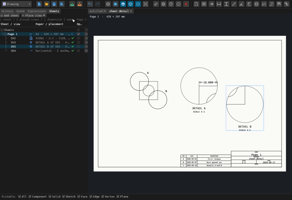
A detail view is a small region of a placed view drawn again, larger: circle the region on the view, and the detail redraws what is inside the circle at a scale of its own.
Press Detail view: the detail is added with no circle and its dialog opens. Pick an anchor for Centre and one for Point on the rim, both on the same placed view. That view becomes the detail's source, and the detail is placed beside it.
- The circle is drawn on the view it was picked on, with the detail's letter beside it. Its radius is the distance between the two anchors, as a length of the model, so the circle keeps round the same feature when you move or rescale that view.
- The detail looks through the same camera as that view — the same direction, the same way up — at twice its scale to start with; change Scale (mm per model unit) in its dialog for any other. Its X and Y are where the circle's centre lands on the paper.
- It draws the model's lines inside the circle and nothing outside it: a line leaving the
circle stops exactly on it, and the detail draws its own boundary circle. Under it the
caption reads
DETAIL Bover its scale,SCALE 4:1. - Which lines show is worked out for the part inside the circle, at the detail's own scale, so a detail at four times the size is drawn four times finer rather than being its source enlarged: a hole seen end-on is one smooth arc.
- Dimension and ordinate it like any placement: its anchors are the points inside its
circle, and a value is a measurement of the model — a 10 mm edge in a 4:1 detail reads
10.000. - Letters are shared with section views — each new one takes the first free letter, whichever kind — and Detail letter in the dialog changes one.
- A detail draws the model only, not the view's annotations: a circle would cut a dimension or a frame in half.
A detail of a detail, and a detail of a section, is not drawn, and says so.
Export
File ▸ Export ▸ Sheet (SVG) writes the open sheet (or the first, if none is open) as
<document>-<sheet>.svg. File ▸ Export ▸ Sheets (PDF) writes every sheet of the
document as one PDF, <document>.pdf: one page per sheet, in the order the Sheets panel lists
them, each page at its own sheet's paper size. Both carry the same drawing at the same size —
the paper's own millimetres, lines and text only, an arrowhead as its outline, a hatch as the
lines it is drawn with and every value as real selectable text — and both include the border,
the title block, the revision table and the sheet's own dimensions, ordinate sets, sections
and details.
The PDF is the drawing set, every page at its true size. The SVG is one sheet with its
structure still in it:
one group per placed view, labelled with the placement, the saved view and the scale; one
more holding the sheet's own dimensions, each labelled with its id, its kind and the value it
read — tolerance included — and, when that tolerance is a PMI dimension's, which one
(data-tolerance-from); one holding its ordinate sets, with a group per station naming the anchor it reads and
its value; inside a section's own view group, its hatch — with the section line in the
group of the view it was cut from; inside a detail's, its boundary and caption — with its circle
in the group of the view it was drawn on; and the revision table as a group of the frame.
The PDF drops that labelling, and its font carries only WinAnsi (Latin-1) characters:
prints as Ø, a deviation's − as -, and a geometric-tolerance symbol as ?. Digits, .,
±, °, / and parentheses print as themselves in both.
This is a different drawing from the Sheet Metal workbench's Export flat pattern (DXF / SVG) button, which unfolds a sheet-metal body.
BOM tables
With a sheet open, use BOM table in the Drawing toolbar. Its sheet form's Tables section lets you select the columns to display, including configured custom part and occurrence attributes. Set the table's position and column width in paper millimetres, or clear Show BOM table to remove it. Selected columns are saved in their selection order. Quantity is derived from the assembly; matching displayed rows of the same part are combined. Find Numbers use the same occurrence attributes as PMI balloons. The table updates with the assembly and is included in SVG and PDF exports, including multi-page PDFs. Each sheet can contain one BOM table.