Sheet Metal Closed Corner
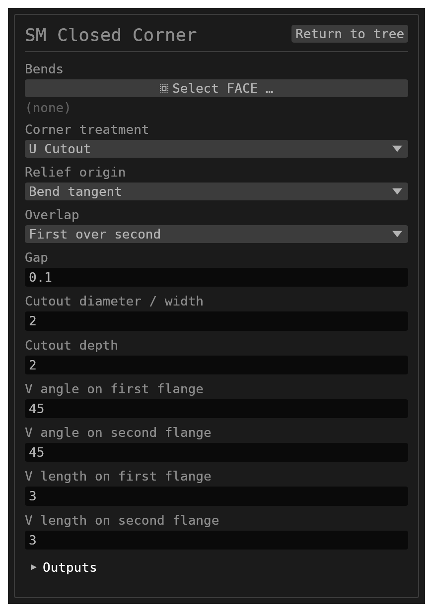
The documentation capture shows every field some choice can show. In the live dialog, only the dimensions of the selected treatment and relief origin appear.
SM.CLOSED_CORNER extends two adjacent flange ends to close their corner, with
a U or V relief at the bend tangency. As in Siemens NX, you select the corner by
its two rounded bend faces. The feature stays editable in history and its
changes carry through to the flat pattern.
- Create two adjacent flanges whose bends fold the same way, at any angles below 180° (they may differ). They may come from one Flange feature or two separate Flange features.
- In the Sheet Metal workbench, choose Home → Sheet Metal → Closed Corner.
- In Bends, select the rounded bend face (inside or outside) of each flange, in order. Flat faces are refused.
- Choose a treatment, overlap direction and gap. Press Enter after editing a numeric value; use Return to tree when finished.
| Control | Effect |
|---|---|
| Bends | The two bend faces at the corner; their order sets overlap and V angles |
| Corner treatment: U Cutout | Rounded-end relief extending from the bend tangent |
| V Cutout | Triangular relief extending from the bend tangent |
| Relief origin: Bend tangent | The default: each wall end is relieved at its own bend tangent (the two rows above) |
| Relief origin: Bend centers | As in NX: one relief centred where the two bend centrelines cross in the flat pattern. It cuts the base plate corner, both bend zones and both walls (see below) |
| Overlap | First selected flange over second, second over first, or Mitre (weld gap): neither overlaps, and both walls are cut on the plane bisecting them, leaving two parallel faces for a weld bead |
| Gap | Overlap: clearance between the butting end and the overlapping flange's inner face. Mitre: the weld gap between the two mitred faces (each wall stops half the gap short of the bisector) |
| Cutout diameter / width | U width at the bend tangent |
| Cutout depth | U/V reach along the wall; U depth must be at least half its width |
| V angle on first / second flange | Bend tangent: angle of each V edge to the direction away from its bend (0° < angle < 90°, default 45°). Bend centers: angle of each flank from its bend's centreline, turned toward that bend's wall (the two sum to less than 90°) |
| V length on first / second flange | Bend centers: length of each V flank from the apex |
The dialog shows only the dimensions used by the chosen treatment. V angles follow selection order even when overlap is reversed.
Documents saved before bend selection picked the flanges' broad faces and could use the Closed or Circular Cutout treatments. They still open and rebuild unchanged. Picking bends in Bends replaces their flange-face selection. Dimensions use document units; angles use degrees.
Reliefs at the bend centers
With Relief origin: Bend centers, the relief is drawn in the flat pattern around the point where the two bend centrelines cross:
- U Cutout: a slot along the corner's bisector, centred on that point. Cutout diameter / width is its width, Cutout depth its overall length (at least the width).
- V Cutout: a notch opening toward the free corner, its apex rounded to Cutout diameter / width (0 for a sharp apex). Each flank has its own angle and length.
The cut goes through the full thickness wherever it meets material: the base plate, both bend zones and both walls. The flat pattern cuts it exactly. In the folded part, a relief edge that crosses a bend at an angle becomes a helical wall. That wall is a B-spline fit within 1e-6 mm (scaled by the bend size) of the true surface; cut walls on the flat faces stay exact. Rebuilding a corner with bend-center reliefs takes a few seconds.
Angles and mitres
At 90° bends with an overlap, the walls are extended as before. At any other angle,
and for the mitre, each wall is extended and trimmed by a plane through the other
wall's geometry: the overlapping wall stops flush with the other wall's outer face,
the butting wall stops the gap short of its inner face, and a mitred wall stops half
the gap short of the bisector. The trimmed end faces are named {wall}:SIDE:cut{i}.
Because a trimmed end can slant through the thickness, the flat-pattern drawing
shows it at the mid-plane.
A flange closed at one end can take a second closed corner at its other end.
Supported geometry
The flanges must be rectangular sibling walls on perpendicular convex edges of the same parent flat, with coincident hinge endpoints, folding the same way by less than 180°. Nested parent flats are supported. A wall may already be closed (and relieved) at its other end; it may not carry further bends. With a 90° overlap the gap must be no greater than the inside radius of the overlapping wall's bend. Relief dimensions must fit within the wall's leg and hinge span. Flange itself cannot yet build a flange over 90° beside another at a shared corner.
The bend sectors and the parent plate keep their shape; the walls are extended and trimmed. This does not reshape a three-bend junction or extend curved bends, and it has no cutout offset or mitre-radius controls.