Assembly Workbench
Id: assembly · Fifth entry in the workbench dropdown
Assembly is for documents that place parts rather than model them: each part is stored once in the document's parts library and placed as many times as you like, and the placements are pinned to one another with constraints.
It offers exactly five features (below): Assembly Component (ACOMP), Pattern Component
(APAT), plus Sketch, Datium and Plane, because sketching on a component face in context is allowed.
Modeling and Sheet Metal do not offer ACOMP;
Wire harness and All do.
When to switch to it
- You want to insert a part and place it — Assembly Component opens the insert-component modal.
- You need the BOM structure tree or the Constraints panel, which are hidden everywhere except here, Wire harness and All.
- You imported a STEP file as an assembly into a document that was not already an assembly — that switches you here automatically, because the panels the structure needs are gated on this workbench. The switch is session-scoped: it does not overwrite your saved boot preference. It is skipped when you are already somewhere that shows those panels (Assembly, Wire harness or All).
- You opened a saved assembly document. Opening restores the workbench the document was saved from, so a document saved here reopens here — but a document saved from Modeling reopens in Modeling, and you have to switch by hand to see its BOM and Constraints.
Panels
Assembly claims two panels, so they appear only here, in Wire harness and in All (see the panel matrix); it also shows every unclaimed one.
- BOM (
assemblyBom) — the component list: every instance, its columns, its actions, then one line per harness wire with its cut length. Click a row, including a nested part's, to select its components; double-click a part at any depth to edit it in place as the Work part, with the rest of the assembly shown translucent and updating live, constraints included (Work part). - Constraints (
assemblyConstraints) — the constraint collection.
The two claims reach further than the dock tabs. The selection context bar follows the same rule, so assembly UI does not leak into Modeling:
- the component menu appears only where the BOM panel is shown. It is ONE menu, the same entries with the same availability and reasons wherever a component is acted on — the selection context bar, the viewport's right-click and the BOM row menu: Make Work Part, Open part, Save part as… (a part with no file of its own only), Edit feature, Move, Unfix and Move (a fixed component only), Move Copy, Replace…, Fix or Unfix, Hide or Show, Info and Delete. Move Copy adds a second instance of the same part (not a new part) on top of the selected one, free to move even when the original is fixed, and arms the move gizmo on it so you drag the copy into place. Open part opens the part in a tab of its own as the Work part: the assembly keeps updating as you edit. Move on a fixed component is greyed with the reason; Unfix or Unfix and Move frees it;
- the constraint offers, and a selected constraint's own Delete, appear only where the Constraints panel is shown.
Moving components
A plain click on a component selects the whole component, and the bar offers the full action set above. Move is also offered on its own when the selection is component geometry — a face, edge or vertex picked with the Component filter off, as you do for constraint work — and when it spans several components:
-
Which component moves. Move always moves the top-level occurrence of the assembly you are editing that owns the picked geometry. A face of a part inside a sub-assembly moves the whole sub-assembly occurrence, as one rigid body; its inner placement is the sub-assembly's own. To move a part inside a sub-assembly, make that sub-assembly the Work part — there the sub-assembly is the document being edited — or open it. While a part is the Work part, the rest of the assembly is context you cannot select, so Move is not offered until you return to the assembly.
-
Several at once. Ctrl-click faces or components in the viewport, or Ctrl/Shift-click rows in the BOM, then press Move: one gizmo, with all of its arrows, rotation rings and centre ball, moves every selected component together as one rigid group. The gizmo sits at the centre of the group's combined bounding box and uses the world axes, and a rotation turns the whole group about that centre. Two faces of the same component count once.
-
Fixed components stay — unless you say so. Move leaves a fixed (grounded) component in the selection where it is; a message names it, and the others still move. When the selection includes a fixed component the bar also offers Unfix and Move: it moves the fixed ones with the rest. They stay fixed until you actually drag (pressing it and changing your mind changes nothing), and the drag unfixes them in the same step, so one Undo re-fixes them and puts everything back.
-
Mates hold while you drag. The assembly is solved on every frame of the drag, for one component or a group: a mated component follows the pointer only as far as its constraints allow, and its partners move with it where the mates carry them. Drag a pin off the axis of the bore it is concentric to and it stays on the axis while you drag. Slide a block that is touch-aligned to a face and it slides along the face. If the mates cannot hold at some pointer position, the component waits at the last position that worked. On a large assembly, where a solve takes longer than a frame, the view shows the last solved position and catches up on later frames. When you let go, one full solve at the final pointer position is written, so the transform shows the solved position, not the dragged one.
-
Undo. A drag is one step, whether it moved one component, a group, or partners the mates carried along: one Undo puts every component back, and one Redo moves them all again.
-
Exact values. While the gizmo is armed, a Move card in the top-left corner of the view takes exact values: Move X, Y, Z in mm along the gizmo's axes, and Turn X, Y, Z in degrees about them, through the gizmo's centre. Type a value and press Enter: the component moves by exactly that much, as if you had dragged that arrow or ring that far, and the field clears for the next one. For one component the axes are the arrows you see, which turn with the component; for a group they are the world axes, about the group's centre. Each value is solved against the mates and is one Undo step, like a drag. A gear, rack or screw partner turns with it. When the mates allow only part of a value, that part is applied and the card's last line says so: "Moved 5 of 8 mm along X, limited by DIST1." When they allow none of it, nothing moves and a message names the constraint holding it. The values are relative to where the component is now. To set an absolute position, edit the component's transform in its feature dialog.
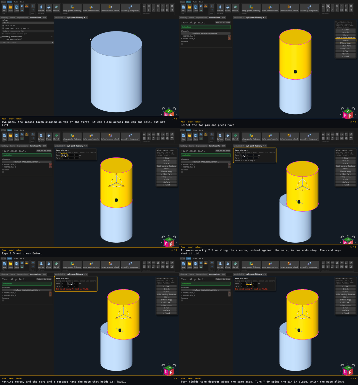
Recorded from the running app by BREP_mcp/tests/videos/assembly-move-typed.json; regenerate every walkthrough
with ./build.sh docs-videos.
One thing deliberately not gated: in every workbench, a modeling feature refuses a reference to component geometry. Sketch, Datium, Plane, Waypoint and Spline may use it — that is how you sketch on a component's face or seat a waypoint on it.
Replacing a component
Right-click a component in the 3D view, or open a BOM row's menu, or use the selection bar, and choose Replace…. The component keeps its place in the assembly: the same occurrence, its pose, whether it is fixed, its BOM occurrence values. Only the part it shows changes.
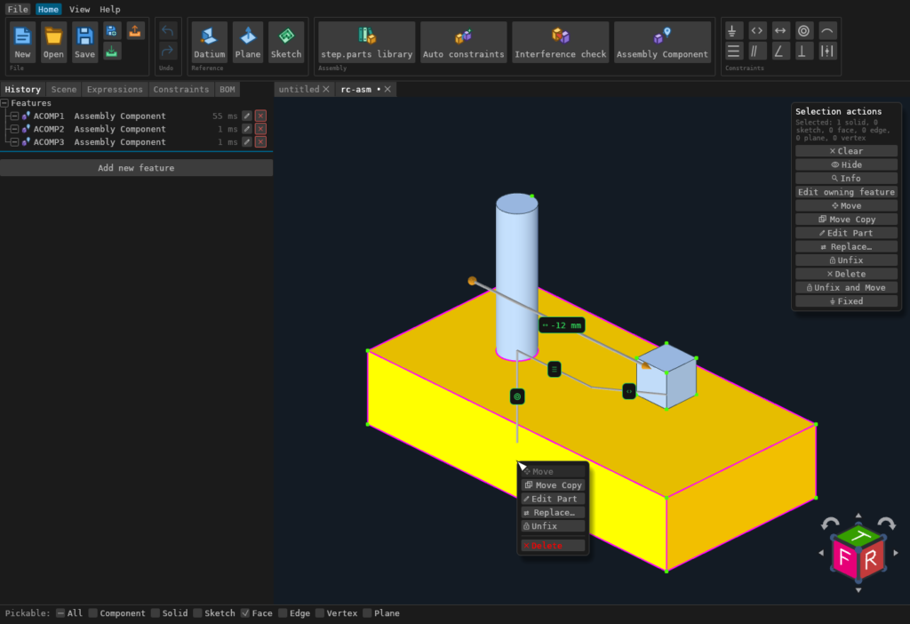
The chooser offers, in this order:
- Same family: the other members of the part's family, by their row name (part number), when the part is a family member.
- In this assembly: the other parts this assembly already uses.
- Same folder: the part files beside it. With the PLM in use, the PLM workspace's parts.
- Recent files, and Browse… for every part file.
Tick Replace all N instances of
Pattern Components follow their seed. Replacing a pattern's seed changes every instance of the pattern in the same step, and the chooser says how many follow. An instance is a copy, not a component of its own: right-click one in the 3D view and its menu reads Instance n of APAT1: follows ACOMP2, offering Open part and Replace…. Both act on the seed, and Replace says so before you choose. The result summary names the pattern and how many instances follow. The pattern keeps its seed even when the seed was picked by a face the new part does not have.
What happens to the mates
A mate remembers the faces it holds by name (ACOMP2:Hole_S), and a part's face names
come from its own features. Whether those names can be trusted depends on how the two
parts are related:
- A member of the same family, or a variation of the same part. A part saved with
Save As remembers what it was saved from, so a copy you edit later is still
recognised as a relative. Every mate whose face still exists keeps it: no mate breaks,
and the assembly re-solves with the new geometry. If the new member's hole is 3 mm
further along, the pin follows the hole. A face that an edit split in two keeps its name
on one piece (the other piece is
<name>_1). Both pieces are the same surface, so the mate holds, and the summary notes the split. - An unrelated part. Two unrelated parts can both have a face called
Extrude1_top, so a matching name proves nothing. Every mate on the replaced component is held (disabled, nothing moves) until you confirm it.
A mate whose face is gone, or whose face is now a different kind of surface (a flat face that became a cylinder), is never moved to another face behind your back. It stays in the assembly, held, and the result summary lists it by name:
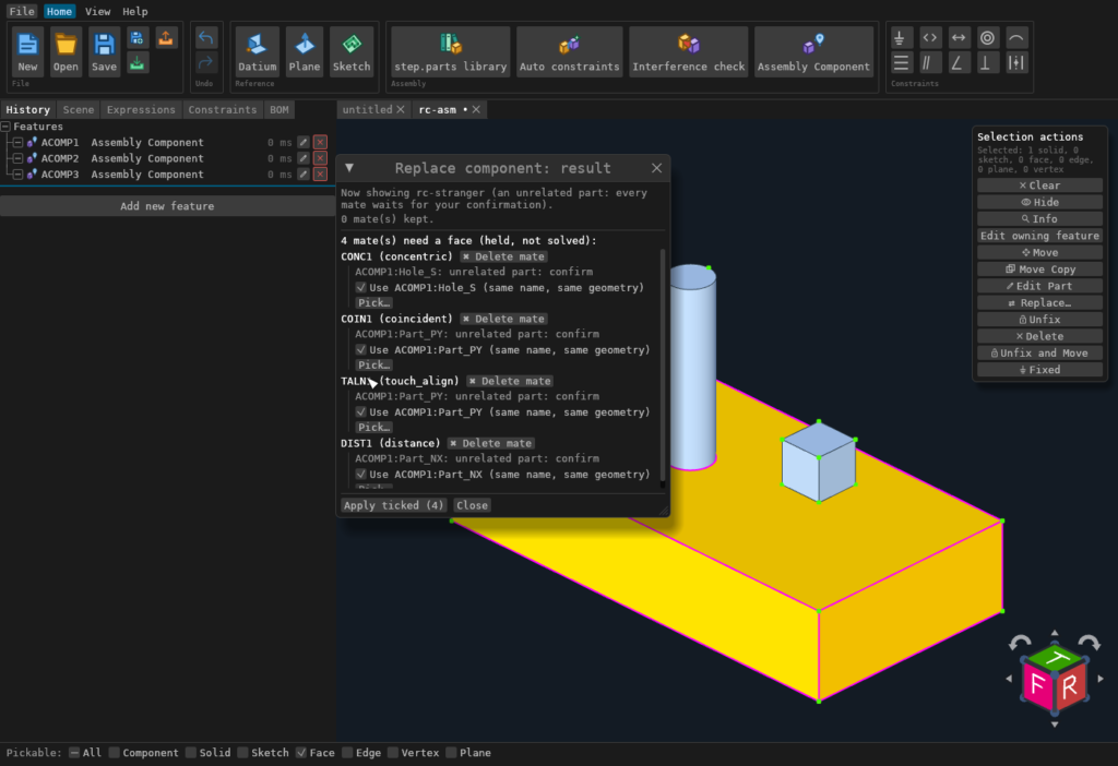
For each held reference the summary offers:
- Use
: the face with the same name, or the nearest face of the same kind. It is ticked in advance only when it is exactly the old surface (the same plane or axis). Apply ticked confirms them. - Pick…: select the face to use in the 3D view, then Use selection.
- Delete mate.
A repaired mate is enabled again (if it was enabled before) and solved. Close the summary whenever you like: held mates stay held, they survive Save and reopen, and the Constraints panel shows ⚠ N mates held after Replace: Review until each one is repaired or deleted.
When a part is edited
A part edit reaches the assembly in two ways: Update components in the BOM, when the part's file changed, and a Work part edit made in place. Either way, the mates on every occurrence of that part are checked once the assembly has rebuilt:
- A mate whose face still exists by name keeps it and follows it. If the edit made the plate 2 mm taller, the pin on top moves up with the top face.
- A mate whose face name is gone is re-attached when exactly one face of the edited part lies on the same surface (the same plane or axis). That happens when a feature is renamed or rebuilt, for example. A message lists each re-attached mate, old face to new face, and nothing moves.
- Anything else is held exactly as after a Replace: disabled, with the nearest face of the same kind suggested. That covers a face that is gone, or a surface that now carries two faces (a channel cut across the top splits it in two). A message names the held mates, and the Constraints panel shows ⚠ N mates held after a part edit: Review, which opens the same summary with Use, Pick… and Delete mate.
One Undo takes back the edit and every re-attachment with it.
Toolbar buttons
The Assembly ribbon group has five large buttons, all also in All:
| Button | Id | Offered | What it does |
|---|---|---|---|
feature:ACOMP | always | Assembly Component — opens the insert-component modal: existing parts-library entries first, with an Upload button for a new file | |
feature:APAT | always | Pattern Component — adds a linear or circular pattern of the selected components; mate the seed and the instances follow (Pattern Component) | |
assembly.step_parts_library | always | step.parts library — opens the online part browser: search, thumbnails, import a STEP part and add it as a component | |
assembly.auto_constrain | always | Auto constraints — infers the mates the components' current placement already implies, and opens the window that lists them | |
assembly.interference | always | Interference check — runs the pairwise intersect sweep now and opens the results window |
Interference check
The window lists every pair of components whose solids overlap, with the overlap volume, largest first, and draws the overlapping volumes in red in the view. Set Clearance (mm) and press Re-run to also list pairs that do not touch but come closer than that, with their gap, smallest first; the gap is drawn as an amber line between the two closest points. The gap is measured on the displayed mesh, so curved faces read within the display tolerance. Click a row to select both components and frame them. Every pair is checked, however large the assembly; pairs whose bounding boxes are apart are cleared without a boolean. A pair whose boolean the kernel refuses (usually exact face contact) is listed as not verified rather than as clear. After the model changes, the drawn volumes are removed until you re-run.
PCB retains a borrowed Add component command because its feature palette does not offer Assembly Component. Assembly and All show only the Assembly Component insertion button.
Selecting a Pattern Component instance offers its pattern's actions instead of the component ones: Suppress instance n, Unsuppress instances (k) while any is suppressed, and Select seed. Move on an instance moves its seed. A mate cannot name an instance; its status says which seed to mate instead.
Auto constraints
An imported STEP assembly arrives fully posed and completely unconstrained: every part sits where the file put it, and nothing holds it there. Auto constraints reads that placement back as constraint intent, so the import becomes editable without re-picking every mate.
The window opens already scanned. Each row is a constraint type it can infer, with what it detects and how many it found; unticking a type re-scans without it, because which types are on changes what the rest accept. Create writes the whole accepted set and solves it as one undo step. A scan never changes anything, so opening the window to look is free.
| Type | Read from |
|---|---|
| Concentric | Axis-bearing faces (cylindrical, conical, toroidal) on two parts that share one centreline. Neither the radii nor the distance along the axis need match — a bolt through a stack of plates is as concentric as a shaft in its bore, so this is the one rule asked about every pair of parts rather than only about neighbours |
| Touch Align | Planar faces on two parts that lie in one plane, face each other (two flush faces pointing the same way are aligned, not touching) and overlap |
| Coincident | Spherical faces sharing a centre, and corners of two already touching parts that land on the same point |
Contact tolerance is how far apart two faces may sit and still read as touching. The default is 0.001 mm; raise it for a file whose parts carry modelled gaps.
When it finds fewer constraints than you expect
It is measuring, so it can tell you why, and it never drops a candidate silently. Two sections under the results account for everything it saw:
- Found but not needed lists candidates it found and deliberately did not create, because the constraints above them already hold the same freedom. Creating them would only over-determine the solve.
- About the faces with no constraint of their own explains the rest. The usual answer is the first line: N more face pairs are qualified on a plane or centreline a constraint above already holds — one mate per carrier is deliberate. Several coplanar faces between one pair of parts are one contact plane and get one mate — a mate per facet would add nothing and over-constrain the result. The remaining lines name the closest pair of parallel faces that missed the tolerance (with the distance, so you can see whether raising it is the fix), how many coplanar pairs face the same way rather than each other, and how many are coplanar but do not overlap.
Because every inferred constraint is read off the pose it is then asked to hold, a healthy assembly does not move when the batch solves. Inferring everything does tend to produce a set the solver calls over-determined — several constraints holding one freedom — which the window reports along with the redundant row count. That is consistent, not a failure; trimming a few constraints afterwards makes later edits easier.
Pairs that already carry a constraint are left alone, so pressing Create a second time creates nothing.
The same work is available to automation as assembly_inferable_types,
assembly_infer_constraints (the read-only scan) and assembly_apply_inferred_constraints.
The workbench actions toolbar carries, besides the four feature buttons, a Constraints group: one button per constraint type (the icons in the table below), each adding that constraint seeded from the selection and opening it in the panel, as the context bar's offer does.
The same icon stands for the constraint everywhere it is shown by picture: the
context-bar offer, the toolbar button, the glyph column of its row in the Constraints
panel, and the chip the viewport draws at the constraint (Show Constraint Graphics). The
chip reads 12.5 mm or 90° for a dimensional constraint and is the bare icon for
the others; hovering it names the constraint (DIST3) and its status, and clicking it
selects the constraint and opens the row. While a reference pick runs (a feature's, a PMI
field's, a clip's or an instructions step's), a chip does not take the click: it goes to the part
under the chip, as if the chip were not there, and the chip keeps its hover text. In the Constraints panel, clicking a row selects
the constraint the same way without opening it (the chip gains its selected outline and the
context bar offers Delete constraint); double-clicking the row, or its , opens its
dialog. The Delete key deletes the selected constraint, or a selected component (its
solids picked in the view or its BOM row), exactly as the row's or the component's Delete
does, one undo step.
Features (5)
| Feature | Code | |
|---|---|---|
| Assembly Component | ACOMP | One placed instance of a parts-library entry: a part reference plus a rigid pose, optionally grounded |
| Pattern Component | APAT | Linear or circular copies of placed components that follow one mated seed |
| Sketch | S | In-context sketching, including on a component face |
| Datium | D | A reference triad of orthogonal XY / XZ / YZ planes |
| Plane | P | One named construction plane |
Constraints are not features
The assembly constraints are a separate catalogue, not features, so they are not in
the Add-feature palette and the workbench feature filter does not apply to them. You add them
from the Constraints panel's + dropdown, which pre-seeds the constraint's elements
from your current selection, filtered by that constraint's own selection filter.
Each one has its own page, with its parameters and an annotated walkthrough of it being applied to a two-component assembly — follow the name.
| Constraint | Short | Elements | Extra parameters |
|---|---|---|---|
| Coincident | COIN | two of vertex / edge / face / component (two faces: coplanar) | facing |
| Touch Align | TALN | two like elements (face / edge / vertex) | facing |
| Parallel | PARA | two elements | facing |
| Distance | DIST | two elements | distance, facing, limit, minimum, maximum |
| Angle | ANGL | two elements | angle, exteriorAngle, limit, minimum, maximum |
| Concentric | CONC | two elements | facing |
| Perpendicular | PERP | two elements | — |
| Tangent | TANG | two elements | — |
| Center | CNTR | three or four: two parallel faces on one component, then one element or two like elements on another | facing |
| Symmetric | SYMM | three: two like elements on two components, then the planar mirror face | — |
| Gear | GEAR | two axes | ratio, reverse |
| Rack and Pinion | RACK | the pinion's axis, then a rack element along its travel | distancePerRevolution, reverse |
| Screw | SCRW | the screw's axis, then a nut element | pitch, reverse |
| Path | PATH | a point and the edge it follows, either order | pinAlong, along, reverse |
| Slot | SLOT | three: the pin, then the slot's two round ends | pinAlong, along, reverse |
| Cam | CAM | the follower (roller, ball or point) and the cam's profile edge, either order | flip |
Every constraint except Center, Symmetric and Slot takes exactly two elements; Symmetric
and Slot take exactly three. The panel's row label appends the evaluated value for Distance and Angle
rows (… 12.500, … 90.0°).
Flip. Each constraint row has ⇅ Flip, which switches the constraint to its other solution as one Undo step:
| Constraint | Flip gives |
|---|---|
| Touch Align, Parallel, Concentric, Center | the component facing the other way (the other facing) |
| Distance from a face | the same distance on the other side of the face (the value, or a limit's range, negated) |
| Angle | the same angle the other way round (negated) |
| Gear, Rack and Pinion, Screw | the coupling turning the other way; nothing moves until the next drag or typed turn |
| Path, Slot | the position measured from the other end |
| Cam | the follower on the other side of the profile |
| Tangent, Perpendicular | the other side, with no setting to change (the next solve stays there) |
Coincident and Symmetric have one solution, so their button is disabled with that reason. To reach the other solution, the component the mate moves is first turned over (or mirrored) and then solved. Which component moves: the one that is not fixed; with both free, the one the mates leave freer.
Conflicts. When constraints cannot all hold, the solve names the smallest set that fights: those rows read Conflict in magenta, their chips in the viewport turn magenta, and each row offers Disable. The most recently added member is marked ★ as the suggestion, and disabling it lets the rest solve. The other constraints read Error: not solved until the conflict is resolved, and nothing moves while it stands.
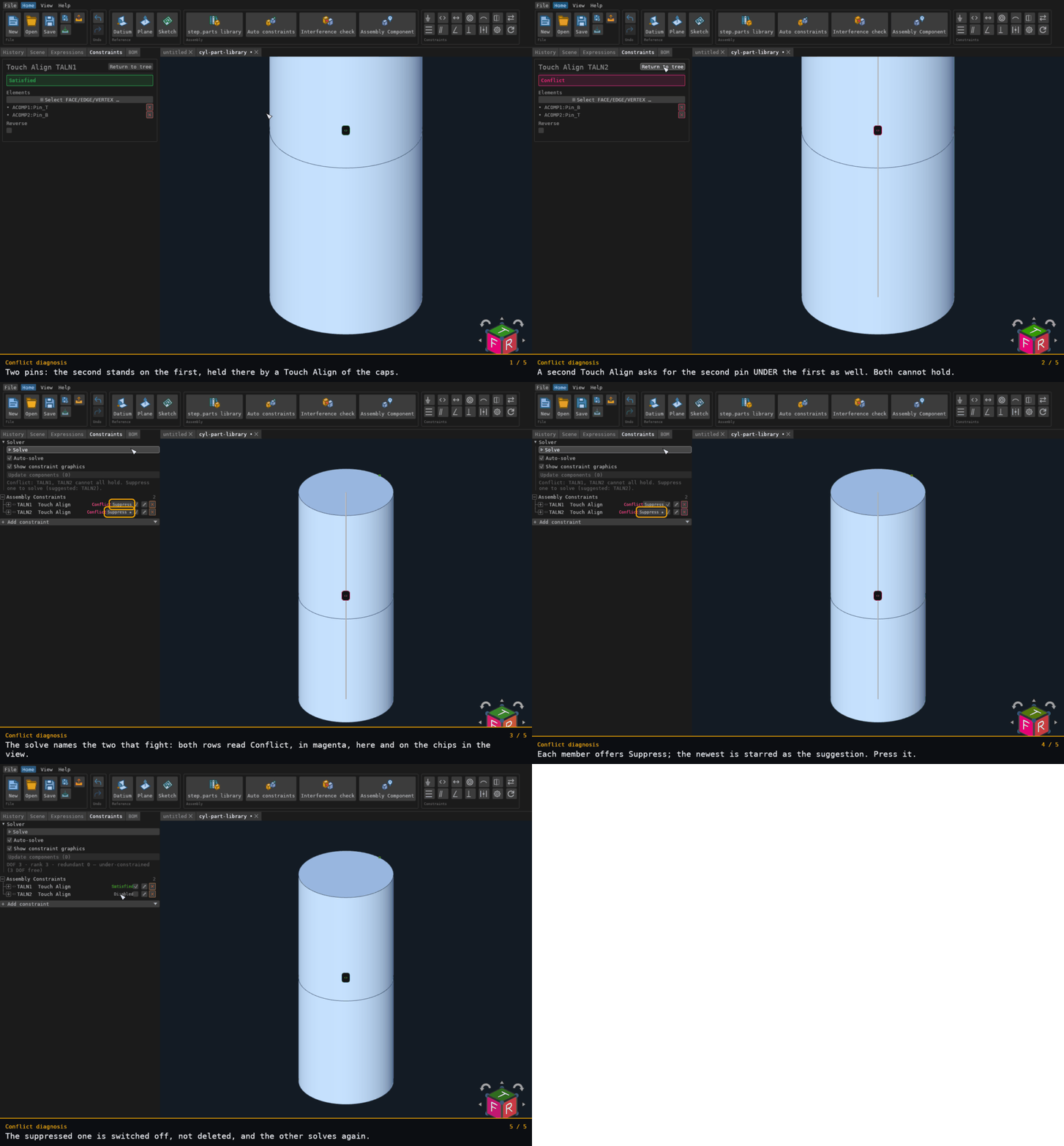
Recorded from the running app by BREP_mcp/tests/videos/assembly-conflict.json; regenerate every walkthrough
with ./build.sh docs-videos.
Limit mates. Turn on limit in a Distance or Angle form and the value is held anywhere between minimum and maximum instead of at one number: the component is free inside the range, and a drag stops at the end it pushes against (Distance, Angle).
Center holds one component centred between two parallel planar faces of another —
a tab in a slot, a pin between two walls. Pick the two faces that bound the width and,
on the other component, either one element (a face, a cylindrical face, an edge or
a vertex: three picks in all) or two like elements (two parallel faces, two parallel
axes or two vertices: four picks). The count is the option: three picks centre that one
element on the mid-plane between the width faces; four picks centre the pair's own
middle — the mid-plane of the two faces, the mid-line of the two axes, the midpoint of
the two vertices — on it. Pick order does not matter: the constraint works out which two
faces are the width (the parallel pair on one component) and which picks are the tab,
and its status message names them. A planar tab is held coplanar with the mid-plane
(the assembled facing is kept as its facing — as for Touch Align), a cylindrical
face or edge has its axis held in the mid-plane, and a vertex sits on it. The two width
faces must be on the same component; centring a part between faces of two different
parts is not supported.
The panel header also carries manual Solve, an auto-solve toggle, the degrees-of- freedom readout (with over-/under-constrained wording), Show Constraint Graphics, and Update components (N) — a batch refresh of components whose source part has changed.
After editing and saving a source model, return to the assembly and open BOM. Click its amber badge or Update components (N) button to load the latest saved sources. Every instance of each changed part rebuilds, including its displayed geometry. The batch is one undo step; saving the assembly preserves the refreshed models. Save the source first: unsaved edits in its tab are not the saved version.
Constraints in the 3D view
With Show Constraint Graphics on, every enabled constraint draws in the viewport: a leader to the geometry it holds and a chip carrying its icon and, for Distance and Angle, its value. Hovering a chip lights the elements that constraint names; clicking one selects it and opens its dialog in the panel.
Right-click a chip, or a constraint's row in the panel, for its menu: ⇅ Flip (the other solution; greyed with the reason for Coincident and Symmetric), Edit, Disable (switch it off without deleting it; a disabled row offers Enable instead) and Delete. The chip and the row offer the same entries and do the same thing.
A Distance draws a real arrow — the perpendicular from its base face to the other
element, in model scale, so its length is the distance — and an Angle draws its
sweep as an arc. Those two are draggable: drag the arrowhead (or the arc's handle) and the
value follows the pointer, with the arrow and the chip tracking it live. The value commits
when you let go, the assembly re-solves, and the components move to match. Dragging an arrow
through its base face takes the distance negative, which puts the other element on the far
side — the same signed convention the distance parameter uses. A drag is one edit: undo
puts the previous value, the previous pose and the previous arrow back. A constraint whose
value is an expression has no handle; edit it in the panel.
How defined is each component?
The BOM marks every component the mates do not fully hold with (−), and its tooltip says what is still free: the mates leave 1 turn and 2 slides free for a block that sits flat on a face. Each solve counts it, per component, from the same analysis as the solver's DOF summary in the Constraints panel. A component with no badge is fully defined; marks a grounded one. See BOM status badges.
Grounding
A component is fixed (grounded: the solve never moves it) by one setting of its own, its
isFixed. There is no Fixed constraint. Fix / Unfix is on the component's row menu in the
components list and the BOM (on a packed BOM row it acts on every placement the row stands
for, as one undo step), in the selection context bar, and as the Fixed checkbox in the
component's dialog; all of them, and component_set_fixed, make the same change, one undo
step. Unfix and Move clears the same setting, in the move's own undo step. A part inside a
flexible sub-assembly is fixed on the instance that lends it. A document saved with Fixed
constraints opens with each one turned into its part's Fixed setting, in place, and a notice
saying so.
The first component of an empty assembly is auto-grounded when isFixed is left unset.
The rule keys on absence, so setting isFixed explicitly to false is always respected —
you can un-ground the sole component. See
Assembly Component.
Sub-assemblies
A sub-assembly placed in an assembly is rigid, as in NX and SolidWorks. Its own
constraints are solved inside the sub-assembly first, the same way they solve when you open
it on its own, and the assembly's constraints then place the whole sub-assembly as one
body. This holds at any depth, and every placed instance of the same sub-assembly arrives
already solved. An assembly constraint may still reference geometry inside a sub-assembly
(ACOMP1:ACOMP2:Pin_S): it moves the sub-assembly as a whole, never one of its parts.
To let an assembly constraint move a part inside a sub-assembly, tick Flexible on that instance (the Assembly Component's edit dialog). Its parts then take part in the assembly's solve, still held by the sub-assembly's own constraints: a pin that its sub-assembly keeps concentric in a bore can slide along the bore to meet an assembly constraint. Parts the sub-assembly grounds stay with it. Each instance is flexible on its own, so two copies of the same sub-assembly can sit in different positions; the positions are saved with the assembly instance, and the sub-assembly's own file is never changed. Flexible covers the sub-assembly's direct parts; a sub-assembly nested inside it still moves as one body.
The assembly does not re-solve the sub-assembly's constraints, but it does report them.
Each one is listed under the sub-assembly's namespace (ACOMP1:CONC1) in the assembly's
solve report (nestedConstraints in the degrees-of-freedom report). A sub-assembly
constraint that does not end satisfied, or that has lost a reference, also adds a note
to the component that places the sub-assembly. The sub-assembly still loads.
Statuses are not saved with a placed sub-assembly. The first time a document is opened, every sub-assembly that has constraints is rebuilt once so its constraints can be solved and their statuses reported. A document saved before sub-assembly constraints were solved this way (builds up to October 2026) may show a part in a different place after that first rebuild. This is expected: the part moves to where its own constraints put it, and the component notes say what changed.
What a document's first runs write back when it opens is part of the open, not an unsaved change. That covers a constraint solved for the first time and the stored picture of a part built again (an assembly imported into the PLM arrives without those pictures). Closing the document without an edit asks nothing. After your first edit, the tab is unsaved as usual. On the PLM, an assembly's copy of a part that has a newer revision is updated when it opens, with a notice. That is not an unsaved change either.
Exploded views
An exploded view pulls the components apart to show how they go together. Open the Exploded views section at the foot of the Constraints pane.
- New exploded view makes one step per component. Each component moves straight away from the base component: the first fixed one, else the largest. Steps are ordered with the outermost component first. spread sets how far, as a multiple of half the assembly's size. Sub-assemblies move as one piece, unless into sub-assemblies is ticked: then each sub-assembly is taken apart too, after the assembly's own components, its parts moving away from its own base. Every step draws a dashed trail from where the component sits. Explode plays a view with many steps in about 4 seconds.
- Show / Hide puts the view on screen and takes it off again, here in the Assembly workbench. Leaving for a workbench that has neither this pane nor PMI hides it, so you never model on exploded parts.
- Explode plays the steps out one after another. ◀ Collapse brings them home. The slider shows any point in between. A part's balloons, and in the PMI workbench its step's label and move gizmo, travel with it.
- + Add step from selection adds a step that moves the selected components, starting just above where they sit, and selects it so you can drag it into place. To move a part inside a sub-assembly on its own, pick its row in the BOM first.
- A step's row selects it, and hovering it lights the step's parts. Drag the move gizmo to place that step by hand. Its box turns the trail on and off, ↑ moves the step earlier, and deletes it.
- Hide selected adds a hide step: the selected components stay out of the view while it is shown (a drawing sheet and a 3D PDF leave them out too). Hide steps are listed under the steps, each with its own ; they are tracked like explode steps (edit, untick, delete, undo), and a view's own hide steps are what decides which parts it hides.
An exploded view is a PMI view whose Explode body annotations are its steps. It is saved with the assembly, the PMI workbench edits it like any view (camera, hidden parts, more annotations), and a drawing sheet or a 3D PDF places it exploded. Where the animation stands is not saved: a view shown again appears fully exploded.
Part attributes
The BOM's part. columns — Part Number, Revision, Material, Mass and the rest — are stored
on each part's own document, so they travel with the part. Editing one from the BOM
writes it back to the part's file; opening that part in its own tab and using the toolbar's
Properties button edits the same record from the other side, with every field shown
whether or not the BOM columns hide it. See Part Properties.
The occurrence. columns — such as Item Number, Reference Designator, Find Number, Notes — describe
one placement, so they live on this assembly and are edited only here.
PMI is a read-only part. column: how many annotations the part's own document carries.
A STEP file imported as an assembly puts an annotation it states about a PART on the part —
once, however many instances place it — so it is not in this document and the
PMI panel cannot show it; the column says which parts have one, and
Open part opens the part that holds it. Annotations the file states about a single
instance land in this document and do show in the panel.
Saving an assembly
Save in an assembly writes the assembly and every part or sub-assembly file that edits
made in the assembly changed. That covers Work part edits, BOM part. cells and nested
occurrence. cells. Parts are written first, then the sub-assemblies that hold them, then
the assembly. A part with no file of its own, or whose file is gone, gets one: a new part
file in the assembly's folder, or its old file written again. Open documents
stay linked: a part edited in its own tab shows in the assembly when you switch to it, and
the other way round. A document that needs a decision (changed on disk, not checked out on
the PLM, a family member) gets a row in one Save dialog. Every row is ticked by
default. See Saving into the parts.
Exporting
STEP export writes the assembly's real structure: one product per parts-library entry, one occurrence per placed instance with its pose, and nested sub-assemblies as nested levels. A part placed twenty times is stored once and placed twenty times in the file.
The BOM exports as CSV or JSON from the ordinary Export dialog — a second row of buttons there, enabled while the document has components or harness wires. It is not gated on this workbench. Each harness wire is its own row with its cut length. See the BOM panel and File Formats.