docs / File Formats: Import and Export
File Formats: Import and Export
Exports are buttons in the Export model dialog, opened by the toolbar's Export… button (the sheet-metal flat pattern has its own button). On desktop a format button then opens the Save file chooser: its explorer picks the folder (the models folder the first time, then wherever the last export went), its name field the file name, and Save writes the file there. In the browser an export is a download, and the browser asks where. Import routing is by extension:
.step/.stpand.iges/.igsare APPENDED to the model as an Import 3D Model feature;.stl,.3mfand.objgo through mesh reconstruction first (RANSAC only for whole-primitive meshes) and are then appended the same way (see STL). A mesh file may hold several bodies: the triangles are split into separately connected shells and each becomes its own solid, all inside the one Import 3D Model feature;- a STEP file that carries an assembly structure offers a choice, and importing it as an assembly appends parts-library entries plus one Assembly Component per occurrence instead of a single Import 3D Model feature;
.nbrepmodel documents are opened throughOpen, each in its own tab..nbrepis the only model extension: a document saved under the retired.BREP.jsonname is not listed until it is renamed to.nbrep(the content is unchanged).
STEP
- Export: ISO 10303-21 AP242, exact B-rep. Recognized analytic carriers export as
native entities (
PLANE/CYLINDRICAL/CONICAL/SPHERICAL/TOROIDAL_SURFACE+LINE/CIRCLE); everything else exports as exact NURBS. Each body is aMANIFOLD_SOLID_BREPnamed by its scene name. Round-trips through the importer with re-recognition. No tessellated/polyline fallback modes exist. The rootPRODUCTtakes the document's name. - Export, structure: a document with assembly
components exports with its product structure, not
as loose bodies. Each parts-library entry becomes its own
PRODUCTholding that part's bodies in the part's own local frame, named by their part-local scene names (Extrude1, notACOMP3:Extrude1). Each placed instance becomes aNEXT_ASSEMBLY_USAGE_OCCURRENCEcarrying its live (post-solve) pose (CONTEXT_DEPENDENT_SHAPE_REPRESENTATION→REPRESENTATION_RELATIONSHIP_WITH_TRANSFORMATION→ITEM_DEFINED_TRANSFORMATION), labelled with the component id so the instance keeps its identity through a round trip. Two instances of one part share ONE product — the geometry is written once. Nested sub-assemblies keep their levels, recursively; a level with no bodies of its own is a bareSHAPE_REPRESENTATION. A document with no components exports as a single flat product. A component's pose is translate + rotate only, so every instance the app can author is rigid; a mirrored or scaled placement reaching the writer another way is refused rather than written as its rotation part (an imported mirrored occurrence already arrives with its non-rigid factor baked into a part of its own). - Export, colours: a body or face carrying a
colorattribute is written with its colour, as theSTYLED_ITEM→PRESENTATION_STYLE_ASSIGNMENT→SURFACE_STYLE_USAGE→SURFACE_STYLE_FILL_AREA→COLOUR_RGBchain every viewer reads, gathered into oneMECHANICAL_DESIGN_GEOMETRIC_PRESENTATION_REPRESENTATION. The attribute is the authority — the colour a STEP import stamped, one picked in the Info window's Metadata tab, or one restored from a saved document — so the file carries exactly the#RRGGBBthe Metadata tab shows. A body or face with nocolorattribute is written with no style, leaving it to the receiving system's default shading; the exception is thehashedBySolidFace color mode, where an uncoloured body is written in the name-derived colour the viewport shows. Override model colors is a display switch and does not change what is exported. On a structured export a part placed several times has ONE written geometry, so it carries one colour per body and face even if the instances were coloured differently. - Export, PMI: the document's PMI rides along as AP242 semantic PMI
per the CAx-IF recommended practices — dimensional location / size / angular location with
nominal values and ± or limit tolerances, datums, the fourteen geometric tolerances with
datum systems, material modifiers and zones — attached to the faces / edges / vertices
through shape aspects. Presentation follows the practice's Graphic (Polyline) Presentation:
every line, arrowhead, frame AND the text (stroked with the PMI font) as
POLYLINEs under oneDRAUGHTING_CALLOUTper annotation, with the type name from the practice's Table 14 and the polyline curve length / centre point / equivalent unicode string validation properties, onANNOTATION_PLANEs (the view's camera-facing plane, plus one on each picked annotation plane), and one saved view (DRAUGHTING_MODEL+CAMERA_MODEL_D3) per PMI view. Leaders and notes are presentation-only; explode annotations are not exported. Checked against OpenCASCADE's XCAF reader. - Import, PMI: AP242 semantic PMI in a file is lifted into the document's
pmiblock beside the Import 3D Model feature — dimensions, tolerances, datums, feature control frames and saved views become live annotations on the imported body. AnANNOTATION_PLANEthat coincides with one of the body's planar faces becomes the annotation's plane (any other plane leaves it view-aligned); free 3D text becomes notes. Annotations no saved view lists land in an "Imported PMI" view. - Import, PMI in an assembly: a file imported as an ASSEMBLY keeps its PMI too, split the way the file states it. An annotation attached to a PART goes into that part's document — once, however many instances place it. An annotation attached to one OCCURRENCE goes into the assembly document, referencing that component's geometry, and the PMI panel lists it beside the file's free notes. The BOM's PMI column counts what each part's own document carries, since the panel cannot show annotations outside the open document. A reference naming geometry the import did not build is kept as an annotation in error, naming the file entity, rather than dropped.
- Import: Part-21 → exact B-rep: analytic + NURBS surfaces/curves,
SURFACE_OF_REVOLUTIONandSURFACE_OF_LINEAR_EXTRUSIONcarriers,SURFACE_CURVE/SEAM_CURVEbundles, seam-crossing edge splits, duplicate-vertex weld, assembly placements,MANIFOLD_SOLID_BREP,FACETED_BREP, certifiedBREP_WITH_VOIDSand closedSHELL_BASED_SURFACE_MODELshells. Validated against OpenCASCADE over the ABC corpus. No feature history is recovered. - Import, structure: a file with a product structure offers a choice — import it as an
assembly (each part stored once in the parts library, one component per occurrence,
sub-assemblies kept by default) or as flat bodies. Assembly import also writes one native
.nbrepdocument per unique part in the current explorer location. When this creates the document's first assembly components, the app switches to the Assembly workbench unless the current workbench already exposes its tools (Assembly, All, or Wire harness). See Import 3D Model. - Import, colours: per-body and per-face colours are read from the file's presentation
entities and stored as a
color(#RRGGBB) attribute, shown in the Info window's Metadata tab. Both are rendered in the viewport: a body colour colours the solid, and a face colour colours that face. - Curve-on-surface geometry on export: every edge is written as a
SURFACE_CURVE(orSEAM_CURVE, when both of its uses are on one surface) carrying a verifiedPCURVEper face, and a collapsed boundary as aVERTEX_LOOP, so an OpenCASCADE-based consumer does not have to reproject every edge or re-detect every periodic seam. A pcurve that cannot be proved to reproduce its 3D curve within the export band is OMITTED and counted in the export report, never approximated. - Import, part numbers: a structured import records each product's
PRODUCT.idas that part'sPart_NumberBOM attribute — the record the Part Properties dialog edits and the BOM reads — so the vendor's part numbers reach the BOM and are written back out on the next export. - Import, mapped items: a
MAPPED_ITEMplaces a shared representation the way an assembly-usage occurrence places a product, and both are read: the item instantiates itsREPRESENTATION_MAP's representation under the composedmapping_target/mapping_origintransform, repeated references become several instances of ONE part, and a mapping nested under an assembly-usage occurrence composes with it. A mirrored mapping is baked into its own mirrored part, as a mirrored occurrence is, so both instances arrive. - Limitations: no parametric tree; PMI presentation imports only as label positions (the
semantic elements are what become annotations); pcurves in an imported file are discarded
and re-derived by projection; some dirty vendor files still import mis-shaped or slowly.
On a structured export, a PMI reference into a part shared by several instances resolves to
the part's one face — annotations on
ACOMP3:topandACOMP4:topland on the sameADVANCED_FACE— but they stay two annotations, each written against the occurrence it was made on, so a re-import puts each back on its own instance. References that resolve to nothing are counted in the export report (pmi_unresolved_references) rather than dropped silently; such an annotation has no geometry to be written against, so it does not survive a round trip. In a NESTED import, an annotation the file pinned below a top-level component has no component of its own to name: it is kept, unresolved, and reported in the import notice.
IGES
- Import reads Manifold Solid B-Rep solids (entity 186) and trimmed-surface sets (144/143) sewn into solids, from other systems' files and our own, through the same builder, checks and refusals as STEP. Every IGES unit is honoured, and the file's stated resolution is checked against its geometry as a STEP file's precision is.
- Assemblies: a file of subfigure definitions (308) placed by instances (408) raises the same contains an assembly choice as a STEP assembly (see Import 3D Model): Import as assembly makes parts-library entries and components; Import as bodies brings every instance in, placed. A part from another file (416) is refused by name.
- Names and colours: a body's name (406 name property, else its label) and colour (314, else the colour number) come in; colours land on the bodies as a STEP file's do.
- Export writes each solid as a Manifold Solid B-Rep with analytic surfaces where the
geometry is a plane, cylinder, cone, sphere or torus, parameter curves on its edges, and its
name and colour. An assembly document exports its structure as subfigures placed by
instances. Automation's
doc_exporttakes the samesolidssubset for IGES as for STEP. - A file the import cannot read correctly is refused with a message that names why; it never imports short.
STL
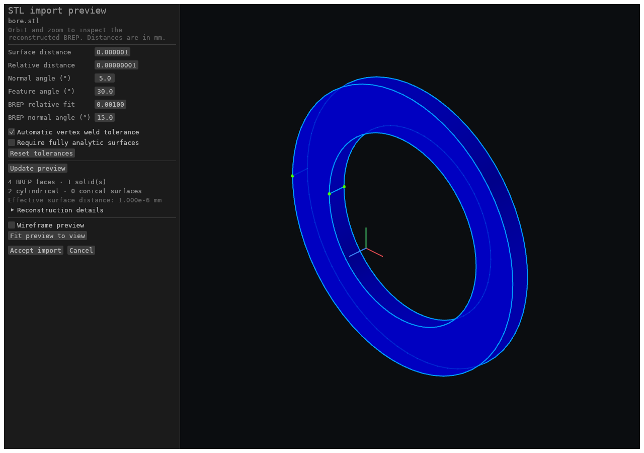
- Export: ASCII STL of the display tessellation. STL carries no unit metadata; coordinates are written in the model's current scale.
- Import: choose a binary or ASCII STL to open an isolated STL import preview. The initial BREP is reconstructed in the background; orbit, zoom, or enable wireframe to inspect its faces before accepting.
- Adjust Surface distance, Relative distance, Normal angle, and Feature angle for recognition. BREP relative fit and BREP normal angle control reconstruction's surface grouping. Vertex welding can use an automatic tolerance or an explicit distance. Absolute distances use mm; relative tolerances scale with the model size.
- Click Update preview after changing tolerances. The old preview is marked outdated, and Accept import stays disabled until the updated BREP is ready. The panel shows BREP face counts, cylindrical/conical surfaces, remaining facets, and effective surface precision. Binary STL's coordinate precision imposes a minimum recognition distance.
- Enable Require fully analytic surfaces to reject results that retain facets. Otherwise, unsupported or unsafe regions may remain faceted BREP faces.
- A defective mesh still gets its cylinders. Surface recognition needs a closed, consistently wound mesh, and a file is often a few triangles short of one — a dropped facet, a duplicated sheet, a degenerate sliver. Such a body is repaired first and recognized from the repaired mesh, so the defect costs only the facets around it. The panel reports the body as not closed, and says what the repair changed.
- A multi-body STL imports as several solids. Triangles that share no vertex belong to different bodies, and each is reconstructed on its own — a print plate, an assembly exported as one file, or a part and its captive pieces arrive as one solid each, with their own names, in one feature. The panel's face and solid counts cover the whole file. Bodies are found by shared corners, so two shells that meet at even a single point are ONE body: if that body is not a valid closed solid the whole import is refused, naming it — nothing is imported in pieces.
- Accept import appends the exact previewed BREP as one undoable Import 3D Model feature. Cancel or Escape leaves the current document unchanged.
OBJ
- Import: offered by the Import picker, through the same mesh reconstruction as STL,
multi-body input included — a file with several
oobjects imports as one solid per separately connected shell. - Export: the OBJ (.obj) button, next to STL. It writes the display tessellation of every solid as one indexed object with per-vertex normals — the same triangles as STL, and likewise with no unit metadata. An empty model reports "nothing to export".
GLB (glTF 2.0)
- Export: the GLB (.glb) button, next to OBJ. It writes the display tessellation as a binary glTF 2.0 file — the same triangles as STL and OBJ, with per-vertex normals and indexed triangles, but one mesh per body, each named by its scene name. It is for viewers, web pages and rendering, not a replacement for STEP's exact surfaces. An empty model reports "nothing to export", and a body with no triangles is skipped.
- Export, axis and units: glTF is right-handed with +Y up, the app's own convention,
so the mapping is the identity, written explicitly as the root node's rotation. The
model's millimetres become glTF's metres through the root node's scale (
0.001), so a 100 mm part measures 0.1 m in a viewer while the vertex buffer still holds100. No vertex is rewritten, so a consumer that ignores the node still reads the model's numbers. - Export, colours: a body or face carrying a
colorattribute is written in that colour — the same attribute STEP reads — and a face's colour beats its body's. A body with no colour takes the colour the viewport shows it in (the Face color setting in the defaultuniformmode, the name-derived colour inhashedBySolid). That is where GLB differs from STEP: glTF has no "no style" state, and a shape with no material renders white and fully metallic. Override model colors does not change what is exported. glTF's base colour is linear, so each sRGB colour is converted with the standard sRGB transfer function, the same one the viewport applies. - Export, materials: one primitive per distinct colour within a body, and one material
per distinct colour across the file (named
color_rrggbb), so two bodies painted alike share a material. Materials are non-metallic at middling roughness. - Not exported: animation, textures or UVs, cameras or lights, PMI, edges and vertices — surfaces only. A document with assembly components exports its bodies flat: the product structure is not carried.
- Import: not supported.
3MF
- Export: the 3MF (.3mf) button, next to GLB. It writes the display tessellation as a
3MF package to the 3MF Core Specification — the same triangles as STL, OBJ and GLB, as
one
<object>per body named by its scene name, placed by one build item each, in millimetres (the<model unit>). It is the format for slicers and print services. An empty model reports "nothing to export", and a body with no triangles is skipped. - Export, mesh: the display mesh keeps a vertex per face so each can carry its normal; 3MF has no normals and wants a closed, consistently wound manifold, so vertices are welded on identical coordinates before writing (a box becomes 8 vertices and 12 triangles) and a triangle that collapses in the weld is dropped. Coordinates are the display mesh's single-precision values. The package is written stored (uncompressed), so it is about the size of its XML — three to four times a binary STL of the same triangles.
- Export, colours: a body or face carrying a
colorattribute is written in that colour — the same attribute STEP and GLB read — and a face's colour beats its body's. Every distinct colour becomes one<base>of a single<basematerials>group (a Core Specification element, so no extension is declared and any core reader sees it): the body's colour is the object'spid/pindex, and a triangle of a differently coloured face carries its ownpid/p1. A body with nocolorattribute is written with no material, the STEP rule rather than the GLB one: 3MF has that state, and an unpainted part should print in the slicer's filament colour, not a grey the app chose. The exception is the same as STEP's: in thehashedBySolidFace color mode an uncoloured body is written in the name-derived colour the viewport shows. Override model colors does not change what is exported. - Export, what slicers show: the colours above are the Core Specification's, read by
readers that honour base materials (this app's own import among them). PrusaSlicer does not
read base materials (its issue #4503, open since 2020); it shows colour only as
multi-material painting, per-triangle extruder assignments stored on the triangle as
slic3rpe:mmu_segmentationor, since PrusaSlicer 2.7.4, as Bambu Studio's (and its forks')paint_color. So every coloured triangle is ALSO written with both painting attributes: each distinct colour, in first-seen order, becomes an extruder slot, up to slot 15 (the painting stores a state in four bits; a colour past that stays a base material without painting). An uncoloured triangle takes the object's default extruder, which is extruder 1, so when the model has any uncoloured triangle the colours start at slot 2 (an unpainted body with one painted face opens as "extruder 1 everywhere, extruder 2 on that face"); a model that is coloured throughout starts at slot 1. A slicer shows painting in its own filament colours, slot by slot, in whatever colours those filaments are set to; the RGB itself stays in the base material. The attribute layout was taken from PrusaSlicer 2.9.2's and Bambu Studio's readers (format references; the encoder is this app's own) and is checked byscripts/three_mf_check.py's independent decoder, not by running a slicer. - Export, not carried: textures, per-vertex colour gradients, the production, slice and beam-lattice extensions, thumbnails, PMI, edges and vertices — surfaces only. A document with assembly components exports its bodies flat: the product structure is not carried.
- Import: offered by the Import picker beside STL, opening the same reconstruction preview with the same tolerance controls and Accept import (see STL).
- Read to the 3MF core specification: the
<model>unit (micron,millimeter,centimeter,inch,foot,meter— millimetres if the file does not say), the<object>resources with their<mesh>vertices and triangles,<components>with their transforms, and the<build>items with theirs. Every coordinate is converted to millimetres. - Repeated instances become separate bodies: one object placed by three build items imports as three solids, each at its own pose, in the single Import 3D Model feature. Component transforms compose inside the item that places them, and a mirrored placement keeps its triangles facing outward. The instances are split into bodies by geometry, exactly as a multi-body STL is, not by the build — so two instances placed so they meet are one body, and a package whose instances overlap that way can be refused.
- Objects marked
support,solidsupport,surfaceorotherdescribe the print job rather than the part, and are not imported. - Import, colours: the Core Specification's base materials are read — a
<basematerials>group'sdisplaycolors, an object's defaultpid/pindexand a triangle's ownpid/p1— and carried through reconstruction by geometry: each body takes the colour most of its source triangles carry, and a face whose own majority differs is coloured on its own, both stored as the samecolorattribute a STEP import stamps and shown in the Info window's Metadata tab. A 3MF this app exported therefore re-imports with its body and face colours. Colour never decides geometry: a triangle naming a group the reader does not know carries none. - Extensions are ignored, not read: the materials extension's colour groups, textures and composites, slices, production UUIDs, beam lattices and thumbnails import as plain geometry (plus whatever base-material colours the file has). A file that marks such an extension REQUIRED is refused.
- The package is read with bounds: encrypted, ZIP64 and multi-part packages, compression
other than stored/deflate, a part that declares an implausible size, and a model that
declares an XML
DOCTYPEare all refused with a message naming the part at fault, as is anything the core specification requires and the file omits.
DXF / SVG (Sheet Metal)
- Export: flat pattern of an unfolded sheet-metal part as DXF or SVG, from the
Export flat pattern toolbar button in the Sheet Metal and All workbenches, which opens the export dialog in its flat-pattern mode. The unfold runs transiently — no feature is added and the history is not modified. The target is the selected sheet-metal body when the selection names exactly one, otherwise the sole sheet-metal body; a part with none errs withno sheet-metal body in the part, and a part with several asks you to select one. One body per export.
SVG (Drawing sheet)
- Export: one drawing sheet as SVG, through the Sheet (SVG)
button — a different drawing from the sheet-metal flat pattern. It is enabled once the
document has a sheet and writes the open one (else the first) as
<document>-<sheet>.svg. The paper size in millimetres is the SVG canvas, each placed PMI view is one group, and the content is lines and text only: the model's visible edges with hidden ones removed, every annotation of the view with its value as selectable text in model units, and the sheet's own marks, border, title block and revision table.
PDF (Drawing sheets)
- Export: EVERY drawing sheet as one PDF 1.4, through the
Sheets (PDF) button, as
<document>.pdf— one page per sheet in Sheets-panel order, each at its own paper size, with the same lines and text as the SVG set in Helvetica. A PDF cannot carry the SVG's grouping or characters outside its font's Latin-1 encoding (a diameter sign prints asØ).
next.BREP.io model (.nbrep)
- Export: the model document, through the Model (.nbrep) button. It is JSON text and
the app's native save format — see Saving and Storage for what it
holds. Besides the feature history it carries the wire-harness block (
wireHarness: the connections, their endpoint addresses such asACOMP3:J1.VCCor a waypoint, their diameters, and thecutMarginthe BOM adds to each wire's length, omitted at 0; routing is recomputed, never stored), the drawing sheets (sheets: paper sizes and the saved PMI views placed on them; the projection is recomputed), and the electronics documents: an assembly's wiring diagram (diagram) and schematic and board (pcb), and a part's symbol (symbol) and pads (pads), each written only once its workbench has edited it. A symbol's pin labels are the names of the part's connection points, and editing either side edits the other. The CAM workbench's setups, tools, operations and NC programs are thecamblock (toolpaths are recomputed, never stored). - Import: reloads the document and recomputes its feature history.
- A family seed (
.fbrep) and a template (.tbrep) are the same JSON document with adocumentClassfield and, respectively, afamilyTableor atemplateInputsblock; a generated member carriesfamilySourceand a part made from a template carriestemplateSource. See Families and Templates.
BOM CSV / JSON
- Export: the bill of materials — one row per referenced parts-library entry, then one row
per harness wire — as CSV or JSON, from a second row of buttons in the Export dialog,
enabled while the document has components or harness wires. It is not gated on the
Assembly workbench. Files are
<name>.bom.csv/<name>.bom.json. - Columns: the CSV header is always
partName,sourceKey,quantity,material,densityGcm3,volumeMm3,massKg,totalMassKg,connectionId,mfQty,status. A part row fills the first eight (the part, its source document, its placement count, and its part's material, density in g/cm³, volume in mm³, mass and quantity × mass in kg — computed from the part's geometry and density, empty when the part cannot give one). A wire row has its stock part number aspartName, quantity1, its connection ID, its cut lengthmfQty(the routed length plus the harnesscutMargin, three decimals) andstatus:current, or why there is no length —routing,cancelled,rolled-back,no-run, or the router's own status such asno-route. A wire without a current length leavesmfQtyempty (nullin JSON); JSON part rows carry the first eight keys. See the BOM panel.