Rib
Status: Implemented
Rib thickens an open sketch polyline into a slab and unions that slab into a target solid — the usual way to add a stiffening web between a wall and a floor without modelling it as a separate body and a Boolean.
Walkthrough
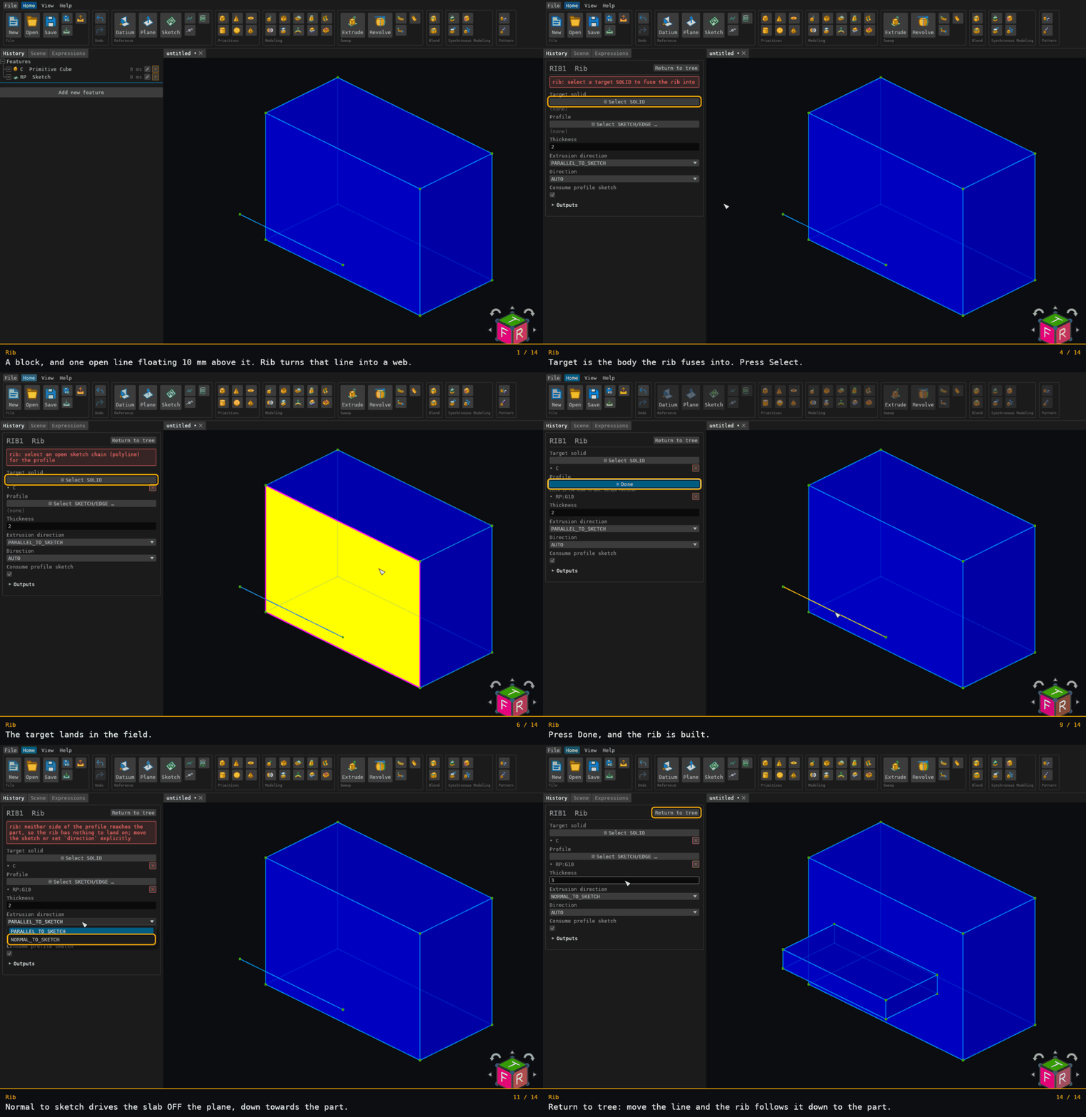
Recorded from the running app by BREP_mcp/tests/videos/rib.json; regenerate every walkthrough with ./build.sh docs-videos.
Inputs
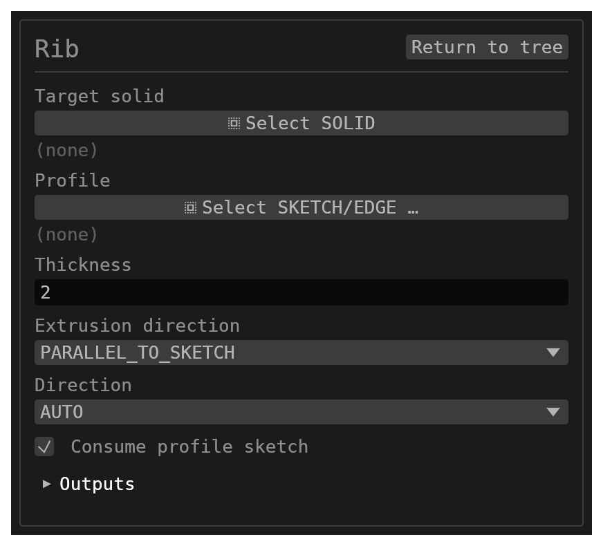
id(string, defaultnull) – optional feature identifier.targetSolid(reference_selection,SOLID, defaultnull,multiple: false) – the solid the rib fuses into. Required.profile(reference_selection,SKETCH/EDGE, default[],multiple: true) – an open sketch chain (a polyline) to thicken; a whole sketch is the supported route.thickness(number, default2) – total rib wall thickness, offset ±thickness/2about the profile.extrusionDirection(options, defaultPARALLEL_TO_SKETCH) –PARALLEL_TO_SKETCHorNORMAL_TO_SKETCH; see Behaviour.direction(options, defaultAUTO) –AUTO,NORMAL, or-NORMAL. Which side of the chain the material goes — SolidWorks' flip material side.consumeProfileSketch(boolean, defaulttrue) – remove the referenced sketch after the rib is created.
There is no depth: see Up To Next below. A depth left in a saved document is ignored.
Behaviour
The two extrusion directions, and why they are not interchangeable
The two follow SolidWorks' Rib.
PARALLEL_TO_SKETCH(default) – the material grows parallel to the sketch plane and the thickness is applied normal to it. Draw a line across the inside corner between a wall and a floor and you get the gusset everybody means by a rib: a thin fin standing on its sketch plane, filling the corner.NORMAL_TO_SKETCH– the material grows normal to the plane and the thickness is applied in it. The chain is thickened inside its own plane and that ribbon is driven off the plane — walls hanging under a sketch.
The two swap which axis carries the thickness and which carries the growth, so the wrong one does not tilt a rib slightly: it lays down the fin that should stand up.
The profile plane
For a SKETCH profile the plane is the one it was drawn on, so a single straight
segment is a good rib profile. A solid EDGE publishes no plane, so the plane is
derived from the chain's own bends.
Which side the material goes
NORMAL and -NORMAL force the ± side of the axis the extrusion direction chose.
AUTO grows the rib toward the part: for a parallel rib it marches out from
points along the chain and takes the side that actually meets material, so it
does not aim a rib out through the open face of a shelled box.
Up To Next
A rib has one end condition, as in SolidWorks: the material grows until it lands on the part, and the feature fails if any part of the rib meets nothing. The rib's far end is the part's own faces, whatever shape they are.
The fuse
The rib is unioned into the target and replaces it under the target's existing name, so every face of the target the rib does not touch keeps its name.
Face names
Every face the rib makes is named from the rib's id and its sketch, so the names survive
rebuilds, rollbacks and upstream edits. Below, {id} is the rib's id (RIB6) and
{segment} is the sketch segment the face was built from, spelled the way the sketch names
it (S5:G10) — picking the whole sketch or one of its segments gives the same names.
| Face | Parallel to Sketch | Normal to Sketch |
|---|---|---|
| The rib's two walls | {id}:A and {id}:B | {id}:{segment}_A and {id}:{segment}_B, per segment |
| The rib's top, along the sketch | {id}:{segment}_TOP, per segment | {id}:TOP |
| The rib's ends, at the chain's first and last point | {id}:START, {id}:END | {id}:START, {id}:END |
A and B are the rib's two sides, and they follow the sketch plane's own normal, not
the order the segments were drawn in. For a Parallel to Sketch rib, {id}:A is the wall on
the side the sketch normal points away from and {id}:B the wall on the side it points
toward. For a Normal to Sketch rib, looking down at the sketch from the side its normal points
to, _B is the wall on the left of the chain as it runs from its first point to its last and
_A the wall on its right. An end or a wall that lands inside the part has no face and so no
name.
When the rib cuts a face of the part in two (a rib across a floor splits the floor), the
piece on the rib's A side keeps the face's name and the piece on its B side is named
after the rib: Floor stays Floor, and the other piece is {id}:Floor_B1. Precisely: the
pieces are taken A side first, then any piece straddling the rib's middle, then the B side,
each side in order along the rib from its first point; the first piece keeps the name, and
every other piece is {id}:Floor_ plus its side letter and its place in that side's count,
the kept piece included. So a second A-side piece is _A2, a straddling piece _M1, and if
every piece is on the B side the first keeps Floor and the next is _B2. Which
piece keeps the name depends only on where the pieces are relative to the rib — never on
which is larger, so moving a hole from one half of the floor to the other renames nothing.
Edge names follow from the face names (Floor|{id}:A[0] where the rib's A wall meets the
floor).
Limitations
- Open straight-polyline profiles only. A profile containing an arc or any curve of degree greater than 1 is rejected, and so is a closed chain.
- A single straight solid edge has no plane for the rib to work in and is rejected. Use a sketch, which knows the plane it was drawn on.
- A parallel rib sweeps the chain along one direction, so a chain that doubles back across its own sweep makes a self-intersecting region and is refused.
thicknessmust be greater than zero.- No target selected is a hard error. A target name that does not resolve is recorded as unresolved and the feature no-ops instead of halting the rebuild.