CAM Workbench
Id: cam · Twelfth entry in the workbench dropdown
CAM (computer-aided manufacturing) programs the machining of the modelled part — what Fusion 360 calls the Manufacture workspace and SOLIDWORKS its CAM add-in. A setup fixes how the part sits on the machine (its work coordinate system, the stock around it and the clearance heights); tools are the cutters in the document's library; operations are machining strategies against picked geometry, each in one setup with one tool; and NC programs are ordered groups of operations posted to a machine. The public capability matrix summarizes supported functions and current limits; this page describes the workbench controls.
Walkthrough
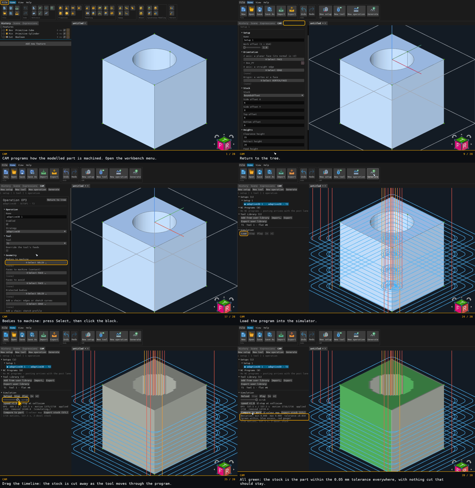
Roughing the seed part (a 20 mm block with a 12 mm hole through it) from start to finish: switch to CAM, add a setup and pick its top face as the machine's Z axis, grow the stock 6 mm around the sides and set the safe heights, add a 6 mm flat end mill, add an operation and choose adaptive3D (adaptive clearing) from its Strategy list, pick the block as the body to machine, set a 1.5 mm load and a 5 mm step-down, Generate, then drag the simulator's timeline through the program and Compare to part: the stock is the part within the 0.05 mm tolerance everywhere. The stock offsets follow the model's axes, not the re-picked Z, so here the sides are X and the model's Z (Top/Bottom offset).
Recorded from the running app by BREP_mcp/tests/videos/cam.json; regenerate every
walkthrough with ./build.sh docs-videos.
What it offers
CAM creates no features: the Add-feature palette is empty here, and the history stays fully editable, because what a setup machines is the model the history already built. It adds:
- the CAM panel — the browser tree: Setups (each with its operations), NC Programs and the Tool Library;
- four toolbar buttons, in the order a program is written (the table below). Each hands the pane its action and brings the pane to the front, and the pane performs it, because the pane owns the selection the action reads — which setup an operation goes into, which tool it uses.
Where the data lives
The part file's cam block, in the shared CAM model's form (the BREP_cam crate's
Setup, Tool and Operation, camelCase, every newer field defaulting): { setups: [{ id, name, modelToMachine, wcs, stock, heights, targets, … }], tools: [{ id, number, name, kind, geometry, holder?, coolant, feeds, … }], operations: [{ id, name, setup, tool, enabled, targets, strategy: { kind, … }, tolerance, stockToLeave, linking, … }], ncPrograms: [{ id, name, number?, post, operations }], idCounter }. Operations are a flat list naming their
setup; the tree nests them under it. A new operation carries every parameter of its
strategy kind at the model's default (cam_state lists the kinds under strategies);
a new tool is a flat end mill of the default geometry; both are edited in their dialogs.
An NC program is an ordered group of operations and the post that writes them — user
input the post lane assembles at post time.
One counter mints every id (SETUP1, T2, OP3, NC4): monotonic, never reused,
rewound by undo with the block it lives in. Every add and delete is its own undo step;
the block is saved with the document and comes back on reopen byte for byte; a document
without CAM data carries no block. A block the app cannot read (a file edited by hand, a
newer format) is reported, never emptied: the pane shows why under its header and
every edit is refused until the document is repaired, so saving never drops what was
there. Toolpaths, mesh snapshots, spatial indexes and stock states are derived and are
never written here — they are regenerated.
The setup dialog
Double-click a setup row (or Edit setup… in its menu, or cam_open) and the pane draws
the setup's dialog in place of the tree: one schema-driven form in five groups.
- Setup — the name and the work offset number (1 = G54).
- Orientation — three picker fields that define the machine frame from the model:
Z axis (a planar face: its outward normal; a cylindrical face: its axis, pointing along
its largest component; a straight edge: its direction from its first point; or a feature's
published axis, such as a helix's
…:Axis: its direction), Flip Z (reverse what the Z reference gives — an axis or an edge has no sense of its own), X axis (a straight edge, re-orthogonalized against Z; absent, the model's X, or its Y when Z lies along X) and Origin (a vertex, or a face's plane point — a cylindrical face's point lies on its axis; absent, the Z reference's point, else the model origin). A face is classified from its own triangles: one that is neither planar nor cylindrical (a sphere, a cone, a freeform face) and an edge that is not straight are refused by name. Press a field and click the entity in the viewport, then Done. The picks are kept with the setup (orientationsin the block) so the frame follows a rebuilt model, and the frame they resolve to is written as the model'smodelToMachine. A pick that no longer resolves (the face was consumed by a later feature) is named in the dialog's banner and the stored transform is left alone. - Stock — the kind (
boundsOffset: side, top and bottom offsets around the bodies;box: two corners;cylinder: base, axis, radius, height;fromSolid: a stock body) and the kind's parameters; the others are hidden. An impossible stock (a box of non-positive size) is refused by the field, with nothing applied. - Heights — clearance, retract and feed, in machine Z; the model's ordering rule (clearance ≥ retract ≥ feed) is enforced on edit.
- Bodies — the bodies to machine and the protected bodies (fixtures, vise jaws), picked as solids.
While a setup is selected or open, the viewport draws its stock box (grey) and its
frame triad at the origin (X red, Y green, Z blue), sized from the stock. The same
geometry is reported under frames in cam_state (origin, axes, stock bounds, or
frameError), which is what the scripts assert.
Machines
A setup is posted for a machine: the setup dialog's Machine group chooses none, one of the built-in machines (a 3-axis VMC, a 4th-axis A table, A/C and B/C trunnions, head-head, head-table, a lathe and a mill-turn, each with its limits, default post and collision solids) or a document machine; generation, the simulation player and an NC program without its own post use it.
The Machines section lists the document's own machines — copies of a built-in made from New machine (one entry per built-in) or from the setup dialog's custom choice. Double-click one (or its menu's Edit machine…) for its editor: name, kind (a change starts the new kind's conventional axis layout), the post, the tool-change time, spindle and feed limits, optional acceleration and travel limits, a 5-axis machine's layout (table-table, head-head, head-table, keeping its two axes), every rotary axis (name, direction, origin, optional angle limits) and a mill-turn's Y axis; the collision solids are counted there. Every value is checked by the model's own rules (a mill-turn's C axis stays on +Z) and a refusal names its field with nothing applied. A machine a setup names cannot be deleted; a built-in is never edited or removed in place — copy it first.
The tool dialog and the libraries
Double-click a tool row (or Edit tool… in its menu, or cam_open) for the tool's dialog, one
form in five groups: Tool (name, number, kind — the model's 21 kinds from flat and ball to
tap, boring bar and lathe insert — description, tool material), Geometry (diameter, cutting
length, shaft, overall length, and the kind's own dimensions: a bull's corner radius, a chamfer's
angle and tip, a lollipop's ball, a tap's pitch; the others are hidden), Holder (none, or a
family — ER16/25/32, side-lock, shrink-fit, hydraulic — with its bore and height, designed through
the holder library), Feeds (spindle speed and direction, cutting and plunge feed, a work
material and Calculate feeds from the material, which runs the feeds calculator on a 3-axis
mill and writes the result) and Coolant. Every edit is validated the way the library validates
a tool, and a refusal names the field with nothing applied.
A tool's row menu also offers Duplicate (a copy under a fresh id and the next number) and
Save to user library. The document's tools are its own library, saved with it; the user
library is kept across documents on this machine (in the app's settings directory, or the
browser's storage), not in a PLM — a PLM-served per-user library is a later PLM slice. The Tool Library section's buttons: Add from user library (a menu of
its tools; one comes in under a fresh id and number), Import… (a Fusion 360 .json / .tools
export, a .csv sheet or a library file, through the file chooser; rows the importer skips are
listed), Export (the document's tools as a library file) and Export user library.
The operation dialog
Double-click an operation row (or Edit operation…, or cam_open) for its dialog, laid out
the way Fusion 360 lays out an operation's tabs:
- Operation — name, enabled, and the Strategy: a new operation starts as a parallel finish;
pick any of the model's strategies from the list (Adaptive clearing is
adaptive3D, 3D pocket clearingpocket3D, …) and the operation takes that strategy's default parameters — the previous strategy's parameters do not carry over; an operation still carrying its automatic name (parallel 1) is renamed with it. - Tool — the tool, from the document's library, and an optional override of its feeds.
- Geometry — the bodies to machine, the faces to machine (contact), the faces to avoid and the protected bodies, each a picker field: press it, click entities in the viewport, press it again for Done. A picked face is kept with the solid that owns it. Two more pickers add chains to machine along (contour, slot, chamfer, trace, engrave): Add a chain: edges or sketch curves takes BREP edges in order (each kept with the body that owns it) or the segments of one sketch, and Add a chain: sketch profile takes a sketch's closed profile. Each chain then has its own group — what it is and its curves, Closed, Reversed, the tool side (auto, left, right, inside, outside, on — inside and outside only on a closed chain), an offset from the chain, an optional start point, a profile's regions by index (empty = every region), and Remove chain. Contour, slot, chamfer, trace and engrave generate along the picked chains: the job carries the chains' sketch curves and profiles from the last history run, so editing the sketch makes the result stale. A chain the generator cannot use yet (an offset, a start point, a side the strategy's own compensation does not match, a profile with islands for contour or chamfer) is that operation's error, with the reason.
- Heights — an optional override of the setup's clearance, retract and feed heights.
- Passes — the machining tolerance, the stock to leave, and then the strategy's own
parameters: the dialog walks the strategy's parameter struct, so a number is a field, a
switch a checkbox, a choice a dropdown of the model's own variants (cut direction,
containment mode, drill cycle…) and a nested group (depths, stepover, containment) a
sub-group. Every strategy the model has — the two-dimensional ones, drilling, the 3D
roughing and finishing families, multi-axis and turning — has a dialog this way, and one
lane C0 adds gets its dialog the day its struct exists.
A strategy with a containment group limits where it cuts. The Machining boundary
is text: loops of
x ypoints in the setup's machine XY, points separated by commas, loops by semicolons (4 4, 16 4, 16 16, 4 16; 8 8, 9 8, 9 9is a square with a triangular hole, since loops count inside by even-odd); empty means the bodies' outline. Machining boundary from a sketch profile picks a sketch's face instead: its loops are sampled within a quarter of the operation's tolerance into the boundary text. The copy is taken when the pick commits and does not follow later sketch edits. A pick that is not a sketch profile, or a sketch not parallel to the setup's machine XY, is refused by name and the boundary stays. The containment mode (tool centre inside, tool inside, tool outside) and an offset of the boundary follow. Slope range (degrees from horizontal) and Z range (machine Z) aremin, max, empty for every slope or level. - Linking — retract policy, keep-down distance, lead-in and lead-out, ramp, arc fitting, smoothing tolerance and safe distance, walked the same way.
Every edit is read back as the model's types and validated by the strategy's own rules; a
refusal names the field or the group with nothing applied. cam_update_operation takes the
same keys as a nested patch (strategy.depths.stepDown, linking.leadIn.kind); a chain is
targets.chains.<index>.side and the like, remove: true drops it, and cam_set_ref with the
field chainEdges or chainProfile adds one by entity names without a pointer.
Typical workflow
- Switch to CAM and press New setup. The setup is selected; double-click it to pick its Z face, X edge and origin, choose the stock and set the heights.
- Press New tool for each cutter the program needs (or add one from the user library, or import a library file). The tool is selected; double-click it to set its kind, geometry, holder and feeds.
- Select the setup (or leave it as the only one), select a tool, and press New
operation. With no setup or no tool the pane says which is missing —
no tool yet: press New tool first— and writes nothing. Double-click the operation to pick its bodies and faces and set its passes. - Press Generate. Every enabled operation with targets is queued on the background
runner, one at a time; the line under the header shows the operation generating, its
phase and count, and the queue, with a Cancel beside it. Each operation's row leads
with its status mark ( idle, ◔ queued, running, generated, ◑ stale, failed; hover
for the count or the reason). An operation whose inputs change after it was generated
reads stale until it is generated again. Each job meshes its bodies at a quarter of the
operation's tolerance (half for scallop, which checks the mesh against half the
tolerance itself), whatever the part's size: a tolerance whose chord falls below
0.0001 is refused by name (
raise the operation's tolerance), and so is a part mesh over four million triangles. A finer tolerance on a curved part costs time. - The generated toolpaths draw in the viewport, each segment coloured by its kind (rapids
and retracts, plunges and drill cycles, cuts and arcs, leads, links), the selected
operation's at full strength and the others dimmed, each taken back to the model through its setup's
frame; an operation's row menu hides or shows its toolpath.
cam_scrub(0..1 along the selected operation's segments) stands the tool's wireframe — cutting part, shank and holder from the tool's own profile — on the toolpath at that point. - Right-click a row for Delete: a setup takes its operations with it; a tool in use by an operation is refused until that operation goes.
Simulation player
Under the tree, the Simulation section plays the generated operations of the selected setup against its stock (lane C17). Load assembles the setup's generated operations into one program (the operations in document order, each with its tool) and seeds the stock from the setup: a box, a cylinder or a solid on screen becomes the Z-dexel grid for a 3-axis stream, or the tri-dexel when any operation tilts the tool axis (3+2, rotary, swarf, contour, multi-axis finishing). The stock is drawn in the viewport in model coordinates; the tool stands at the scrub position with its shank and holder, along the motion's tool axis.
- Play / Pause, |< and >| (to the start or end of a motion), the scrub slider over the program's
time, and speed (× machining time). Material is removed per whole motion, in chunks of motions per frame, so
the readout shows
appliedcatching up to the scrub position; scrubbing back replays from a checkpoint. - The readout: operation, time / total cycle time (C7's estimate: rapids at the machine's rapid rate, cuts at their feed, acceleration when the machine states one), motion, applied count, removed volume.
- stop at collision: for a 3-axis stream the checked simulation marks every collision (shank, holder, or the cutting part on a rapid) and gouge at load, draws them as red points, and playback pauses when such a motion is entered.
- Compare to part: the deviation of the simulated stock from the setup's target bodies (C7's map: positive is excess stock, negative a gouge, signed by the normal distance), shown as a colour map on the stock (green within tolerance, blue excess, red gouge) with a legend; colour map toggles it.
- Export stock (STL) saves the simulated stock as ASCII STL through the save door.
Toolbar buttons
| Button | Id | Offered | What it does |
|---|---|---|---|
| New setup | cam.new_setup | always | Adds a setup (work coordinate system, stock and heights) and selects it |
| New tool | cam.new_tool | always | Adds a tool to the document's library with the next free tool number and selects it |
| New operation | cam.new_operation | always | Adds an operation to the selected setup with the selected tool, or says which is missing |
| Generate | cam.generate | always | Queues every enabled operation on the background runner; the pane shows progress, Cancel and each operation's status |
Automation
Every action is a command: cam_state, cam_add_setup, cam_add_tool,
cam_add_operation, cam_add_program, cam_remove, cam_select, cam_open,
cam_update_setup (a patch of the dialog's keys), cam_set_ref (a setup's or an
operation's picker field by entity name, no pointer), cam_update_tool, cam_duplicate_tool,
cam_calculate_feeds, cam_library (list / save / add / remove / import / export),
cam_update_operation (a nested patch of the operation form's keys), cam_generate (every
enabled operation or ids; returns what was queued and what was refused and why),
cam_cancel, cam_toolpath (one operation's generated motion stream and report),
cam_toolpath_visible (the row menu's Hide / Show toolpath), cam_scrub, cam_add_machine and
cam_update_machine (a nested patch of the machine editor's keys), beside
workbench_button for the four buttons. The __brepCam state blob
carries the block with the pane's selection and last notice, generation (busy, the
operation in flight, the queue, progress, every result's summary) and statuses (each
operation's idle / queued / running / ok / stale / error); __brepCamHit carries the pane's
rects (cam:*). A toolpath is never written to the document: wait_state on
/__brepCam/generation/busy eq false waits for a generation. The cam-workbench,
cam-setup, cam-orientation, cam-axis-orientation, cam-tools, cam-operation, cam-containment, cam-generate, cam-chains, cam-machines and cam-broken-block scripts in
the MCP suite drive all of it.
The simulation player: cam_sim_load, cam_sim_state (also the __brepCamSim blob), cam_sim_play,
cam_sim_scrub, cam_sim_step, cam_sim_set, cam_sim_deviation, cam_sim_export, cam_sim_unload; its widgets
are the cam:sim:* hit keys of the CAM pane.